WDM(Wavelength Division Multiplexing) is a technology that combines two or more optical carrier signals(carrying various information) of different wavelengths at the transmitting end with multiplexers and coupling them to the same optical fiber for transmission. At the receiving end, the optical carriers of various wavelengths are separated by a Demultiplexer, then get further processed by the optical receiver to recover the original signal. This technique of transmitting two or more different wavelengths of optical signal simultaneously in the same optical fiber is called Wavelength Division Multiplexing.
The WDM device has two sides:
Client Side: The Client’s services such as SDH/IP/ATM are accessed from this side interface, also known as the business side.
WDM Side: output the standard OTN color optical signal after processing the customer side signal.
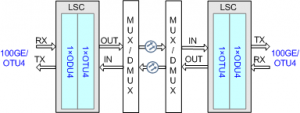
The LSC board is a wavelength conversion board and applies to coherent systems. For the position of the LSC board in the WDM system, see figures below:
Position of the LSC board in the WDM system
Position of the LSC board in the WDM system (regeneration mode)
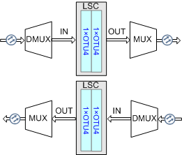
Only the TN17LSC/TN18LSC board supports the regeneration mode.
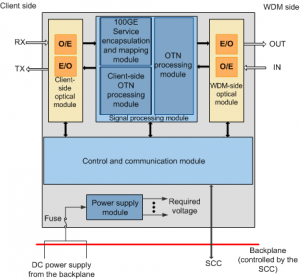
The LSC board consists of the client-side optical module, WDM-side optical module, signal processing module, control and communication module, and power supply module.
Figures below show the functional modules and signal flow of the LSC.
Functional modules and signal flow of the LSC board
Functional modules and signal flow of the LSC board (regeneration mode)
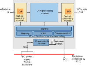
In this article, we will mainly explain the differences between TN17LSC and TN18LSC,which are both 100G OTU boards, in main functions, front panel, valid slots, mappings, variants, versions, substitutions, updates, optical modules……
- Front Panel
TN17LSCboard occupies two slots, the TN18LSC board occupies one slot.
Front panel of the TN17LSC board:

Front panel of the TN18LSC board:
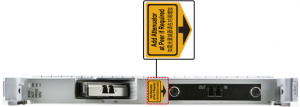
If an optical attenuator is required between a TN18LSC board and an interconnected board, you must install the optical attenuator on the optical port of the interconnected optical multiplexer/demultiplexer board. Otherwise, the cabinet door will squeeze optical fibers.
If the equipment is installed in a Huawei cabinet, the board can only use G.657A2 fibers; otherwise, the fibers will be pressed by the cabinet door. If the cabinet door is not required or if the equipment is installed in a third-party cabinet whose door does not press the fibers, there is no restriction on the fiber type.
- Valid Slots
Two slots house one TN17LSC board, one slot house one TN18LSC board.
Valid slots for the TN17LSC board:
| Product | Valid Slots |
| OptiX OSN 8800 T64 subrack | IU1-IU7, IU11-IU17, IU19-IU25, IU27-IU33, IU35-IU41, IU45-IU51, IU53-IU59, IU61-IU67 |
| OptiX OSN 8800 T32 subrack | IU1-IU7, IU12-IU18, IU20-IU26, IU29-IU35 |
| OptiX OSN 8800 T16 subrack | IU1-IU7, IU11-IU17 |
| OptiX OSN 8800 universal platform subrack | IU1-IU15 |
| OptiX OSN 6800 subrack | IU1-IU16 |
The TN17LSC board occupies two slots. The rear connector for connecting the TN17LSC board to the backplane is located in the left slot of the two slots. Therefore, the slot number for the TN17LSC board is displayed as the left slot of the two slots on the NMS.
For example, if the TN17LSC board is housed in the slots IU1, and IU2, then the slot number for the TN17LSC board is displayed as IU1 on the NMS.
When TN17LSC boards are used as regeneration boards and ESC communication is required, the transmit-end and receive-end TN17LSC boards for the same wavelength must be configured in paired slots. This restriction does not apply to other scenarios.
Valid slots for the TN18LSC board
| Product | Valid Slots |
| OptiX OSN 8800 T64 subrack | IU1-IU8, IU11-IU18, IU19-IU26, IU27-IU34, IU35-IU42, IU45-IU52, IU53-IU60, IU61-IU68 |
| OptiX OSN 8800 T32 subrack | IU1-IU8, IU12-IU19, IU20-IU27, IU29-IU36 |
| OptiX OSN 8800 T16 subrack | IU1-IU18 |
| OptiX OSN 8800 universal platform subrack | IU1-IU16 |
When ESC is used for communication, any two TN18LSC boards that are used to regenerate the same wavelength must be installed in any of the following slot pairs:
- Main functions
| Board | Type | Client-Side Service | Pluggable Optical Module | WDM Specifications | |||
| Type | Max. Number | Client Side | WDM Side | DWDM | CWDM | ||
| TN17LSC | Non-convergence | 100GE, OTU4 | 1 | Y | N | Y | N |
| TN18LSC | Non-convergence | 100GE, OTU4 | 1 | Y | Y | Y | N |
The only difference is TN17LSC cannot support WDM Side pluggable optical module.
- Mappings
The only difference is TN18LSC cannot be supported by the OSN6800 Subrack.
| Board | TN17LSC | TN18LSC |
| Initial Version | V100R010C00 | V100R010C10SPC300 |
| General 8800 T64 Subrack | Y | Y |
| Enhanced 8800 T64 Subrack | Y | Y |
| General 8800 T32 Subrack | Y | Y |
| Enhanced 8800 T32 Subrack | Y | Y |
| 8800 T16 Subrack | Y | Y |
| 8800 Universal Platform Subrack | Y | Y |
| 6800 Subrack | Y | N |
| 3800 Chassis | N | N |
- Variants
| Available variants of the TN17LSC board | ||
| Variant | WDM-Side Fixed Optical Module | FEC Encoding |
| T50 | 150000 ps/nm-C Band-Tunable Wavelength-ePDM-QPSK(SDFEC2, Enhanced)-PIN | SDFEC2 |
| T51 | 150000 ps/nm-C Band-Tunable Wavelength-ePDM-QPSK(SDFEC2)-PIN | SDFEC2 |
| T52 | 55000 ps/nm-C Band-Tunable Wavelength-ePDM-QPSK(SDFEC2)-PIN | SDFEC2 |
| T53 | 40000 ps/nm-C Band-Tunable Wavelength-ePDM-QPSK(SDFEC2)-PIN | SDFEC2 |
| T61 | 150000 ps/nm-C Band-Tunable Wavelength-ePDM-QPSK(SDFEC2, wDCM)-PIN | SDFEC2 |
| T62 | 40000 ps/nm-C Band-Tunable Wavelength-ePDM-QPSK(SDFEC2, wDCM, LH)-PIN | SDFEC2 |
| T65 | 12000 ps/nm-C Band-Tunable Wavelength-ePDM-QPSK(SDFEC2,wDCM-Metro)-PIN | SDFEC2 |
| T58 | 120000 ps/nm-C Band-Tunable Wavelength-ePDM-QPSK(SDFEC2)-PIN | SDFEC2 |
| T68 | 120000 ps/nm-C Band-Tunable Wavelength-ePDM-QPSK(SDFEC2, wDCM)-PIN | SDFEC2 |
| NOTE: | ||
| The T65 variant of the TN17LSC board applies to metro networks, and its WDM-side module requires the use of the same wavelength at the transmit and receive ends and does not support wavelength change by configuring regeneration boards. | ||
| Table 5 Available variants of the TN18LSC board | ||
| Variant | WDM-Side Pluggable Optical Module | FEC Encoding |
| T5U | 40000ps/nm-Extended C band-Tunable Wavelength-ePDM-QPSK(SDFEC2, ULH+, T5U)-100G CFP | SDFEC2 |
| T62 | 40000ps/nm-Extended C band-Tunable Wavelength-ePDM-QPSK(SDFEC2 , wDCM, LH, T62)-100G CFP | SDFEC2 |
| T65 | 12000ps/nm-Extended C band-Tunable Wavelength-ePDM-QPSK(SDFEC2 , wDCM-Metro, T65)-100G CFP | SDFEC2 |
| TxA | 40000ps/nm-Extended C band-Tunable Wavelength-ePDM-QPSK (configurable FEC, coherent/wDCM, ULH+, TxA)-100G CFP | SDFEC2, HFEC PLUS |
- Differences Between Versions
| Board | Latency Measurement | FEC Encoding |
| TN17LSC | Y | SDFEC2 |
| TN18LSC | Y | SDFEC2/HFEC PLUS |
- Substitution Relationship
| Original Board | Substitute Board |
| TN15LSC | TN17LSC |
| TN17LSC | None |
| TN18LSC | None |
The TN17LSC can be created as 15LSC on the NMS. The former can substitute for the latter, without any software upgrade. After the substitution, the TN17LSC board functions as the TN15LSC board.
When both the receive and transmit boards employ SDFEC2, the substitution applies. The TN15LSC board cannot be replaced with the TN17LSCT62 and TN17LSCT50 board.
Both TN18LSC and TN17LSC do not have substitute boards.
- Update Description
This describes the hardware updates in V100R006C03 and later versions as well as the reasons for the updates.
| Hardware Updates in V100R011C10 | |
| Hardware Update | Reason for the Update |
| The TN17LSC board supports the regeneration mode. | The function is enhanced. |
| Hardware Updates in V100R011C00 | |
| Hardware Update | Reason for the Update |
| Added the TN18LSC board. | The TN18LSC and TN17LSC boards have the same functions, and the differences between them are as follows: |
| Compared with the TN17LSC board, the TN18LSC board occupies one slot. | |
| Compared with the TN17LSC board, the TN18LSC board supports extended C-band. | |
| Compared with the TN17LSC board, the TN18LSC board supports WDM-side pluggable optical module. | |
| The TN18LSC board supports the regeneration mode. | |
| Added the TN17LSCT62 and TN17LSCT50 board. | TN17LSCT62: The board supports ePDM-QPSK(SDFEC2, wDCM, LH). |
| TN17LSCT50: The board supports ePDM-QPSK(SDFEC2, Enhanced). | |
| Hardware Updates in V100R010C00 | |
| Hardware Update | Reason for the Update |
| Added the TN17LSC board. | The TN17LSC and TN15LSC boards have the same functions, and the differences between them are as follows: |
| Compared with the TN15LSC board, the TN17LSC board consumes less power. | |
- LSC Specifications
The specifications vary according to the version of boards that under use.
| Board | Client-Side Pluggable Optical Module | WDM-Side Fixed Optical Module | WDM-Side Pluggable Optical Module |
| TN17LSC | 100G BASE-LR4-10 km-CFP | 150000 ps/nm-C Band-Tunable Wavelength-ePDM-QPSK(SDFEC2)-PIN | N/A |
| 100G BASE-10×10G-10 km-CFP | 55000 ps/nm-C Band-Tunable Wavelength-ePDM-QPSK(SDFEC2)-PIN | ||
| (100G BASE-4×25G)/(OTU4-4×28G)-10 km-CFP | 40000 ps/nm-C Band-Tunable Wavelength-ePDM-QPSK(SDFEC2)-PIN | ||
| 150000 ps/nm-C Band-Tunable Wavelength-ePDM-QPSK(SDFEC2, wDCM)-PIN | |||
| 12000 ps/nm-C Band-Tunable Wavelength-ePDM-QPSK(SDFEC2,wDCM-Metro)-PIN | |||
| 120000 ps/nm-C Band-Tunable Wavelength-ePDM-QPSK(SDFEC2)-PIN | |||
| 120000 ps/nm-C Band-Tunable Wavelength-ePDM-QPSK(SDFEC2, wDCM)-PIN | |||
| 40000 ps/nm-C Band-Tunable Wavelength-ePDM-QPSK(SDFEC2, wDCM, LH)-PIN | |||
| 150000 ps/nm-C Band-Tunable Wavelength-ePDM-QPSK(SDFEC2, Enhanced)-PIN | |||
| TN18LSC | (100 GBASE-4×25G)/(OTU4-4×28G)-10 km-CFP2 | N/A | 40000ps/nm-Extended C band-Tunable Wavelength-ePDM-QPSK(SDFEC2, ULH+, T5U)-100G CFP |
| 100G BASE-ER4-40 km-CFP2 | 40000ps/nm-Extended C band-Tunable Wavelength-ePDM-QPSK(SDFEC2 , wDCM, LH, T62)-100G CFP | ||
| 100G BASE-SR10-100 m-CFP2 | 12000ps/nm-Extended C band-Tunable Wavelength-ePDM-QPSK(SDFEC2 , wDCM-Metro, T65)-100G CFP | ||
| 40000ps/nm-Extended C band-Tunable Wavelength-ePDM-QPSK (configurable FEC, coherent/wDCM, ULH+, TxA)-100G CFP | |||
| NOTE: | |||
| Configurable FEC types: SDFEC2, HFEC PLUS. | |||
| In a coherent network, the recommended modulation format for the TxA module is QPSK. | |||
| In a wDCM network, the modulation format can only be QPSK wDCM for the TxA module. | |||
| The QPSK and QPSK wDCM modulation formats cannot interconnect with each other. |
The LSC board is a wavelength conversion board and applies to coherent systems. In the receive direction, the board receives one 100GE/OTU4 optical signal from the client equipment, maps the optical signal into an OTU4 signal, and converts the OTU4 signal into a standard WDM wavelength.
TN17LSC boards are not common in the market, so we recommend can take TN18LSC as alternatives, because they have the same SDFEC2 coding way, just dispersion tolerance of TN18LSC is 40000 ps/nm while TN17LSC is 150000 ps/nm.
But 40000 ps/nm can reach 2400 km, if the distance is not more than 2400 km, there is no necessary to need 150000 ps/nm.
For more detailed information and solutions, please feel free to contact csd@telecomate.com for help.

Leave a comment