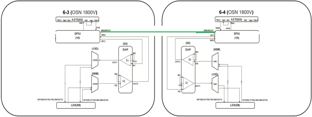
In this post, I will share the commissioning of the Optical Power of OptiX OSN 1800 V. I hope you’ll like it!
Scenario Description
1. Two OptiX OSN 1800V support two OCh trails in point-to-point networking mode.
Topology:
2. Optical fiber connection (Both physical and logical fibers are connected, and no Spectrum Analyzer Board is available)

3. On the DAP board, OA module 1 is TN15OAC101, and module 2 is TN15OAC106.
Board specifications:

Optical Power Commissioning
1. Commission the optical power of the OSC trail.
Open the NE Explorer and check the receive optical power of TM1/RM1 on the AST2 board. The receive optical power of NE (6-3) exceeds the upper limit (-10 dBm). A 10 dB fixed optical attenuator needs to be added for RM1. Similarly, a 5 dB fixed optical attenuator needs to be added to RM1 of NE (6-4).
For the optical power of the OSC trail, because the threshold range of the optical module is large, the actual receive optical power only needs to be within the range of the upper threshold – 5 and the lower threshold + 3. If sufficient time is available, adjust the value to the middle of the upper and lower thresholds.
2. Commission the optical power of OCH trails from NE (6-3) to NE (6-4).
Operations on NE (6-3)
a. Check whether the two WDM-side optical modules of the LDX board emit light normally.
b. Checked the optical power of port VI_2 on the DAP board. It was found that the optical power of port IN_2 was –3 dBm. The optical power of port IN_2 should be adjusted to -9dBm (-12+10lg2≈-9). The VOA value of VI_2 needs to be set to 6. If the expected value cannot be obtained after the setting, it needs to adjust the VOA value several times.
Operations on NE (6-4)
In the receiving direction of an OTM site, do not need to strictly follow the nominal input and output values of the OA board. It only needs to ensure that the optical power is within the allowed range of the OA board.
a. Check the optical power of the VI_1 port on the DAP board. It is found that the optical power of the VI_1 port is 9 dBm and that of the IN_1 port is –15.9 dBm.
b. Query the receive optical power of the two WDM-side ports on the LDX board. If the value is -60 dBm, the value of the IN_1 port is lower than the threshold that the OA module can receive. As a result, the OA module fails to work.
C. Decrease the VOA value of VI_1 (temporarily set to 16) to increase the value of IN_1 to ensure that the OA module can work properly.
D. Query the received optical power of the LDX board again. It is found that the receive optical power of the LDX board changes to -14 and -13.7. Query the received optical power of the port from -16 to -2. The ideal receive optical power is (-16 + (-2))/2 = -9. Perform several minor adjustments to distribute the receive optical power around -9 dBm.
If the equipment uses the EX40V board, we can adjust each wavelength to -9 dBm.
3. Commission the optical power of two wavelengths from NE (6-4) to NE (6-3).
First Operations on NE (6-4)
Adjust the VOA value of VI_2, in the same way, to make the value of IN_1 reach -9 (-12 + 10lg2 ≈ -9).
Operations on NE (6-3)
A. Query the receive optical power of the LDX board. It is found that the receive optical power is greater than the ideal value – 9. Increase the VOA value of VI_1.
B. However, it is found that the VOA value of VI_1 is the default maximum value (21.5). The solution is to reduce the transmit optical power of the upstream station.
Continue back to NE (6-4)
Slightly increase the VOA value of VI_2 to decrease the input optical power of the OA module, so that the LDX receive power of NE (6-4) is around -9 dBm.
Query the FEC performance of the WDM ports at both ends
Navigation: Monitor/WDM Performance
If the FEC performance value is not 0, troubleshoot the fault. In addition to checking the optical power, you also need to set port parameters and board working temperature parameters.
If you have any questions, please feel free to contact: csd@telecomate.com.


Leave a comment