
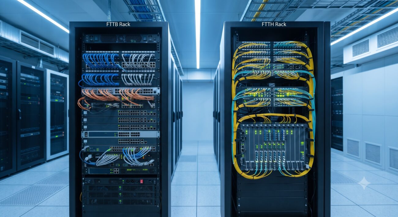
STRATEGIC HARDWARE POSITIONING
This document provides a comprehensive Total Cost of Ownership (TCO) and capital expenditure (CAPEX) evaluation framework for network operators transitioning from Fiber-to-the-Building (FTTB) to Fiber-to-the-Home (FTTH) architectures. As global bandwidth demands surge and the average revenue per user (ARPU) increasingly correlates with ultra-broadband service tiers, the economic inflection point favoring FTTH has become indisputable for greenfield deployments and is now compelling for many brownfield upgrades. This report dissects the hardware, operational, and lifecycle cost drivers to inform strategic procurement decisions.
TCO EFFICIENCIES
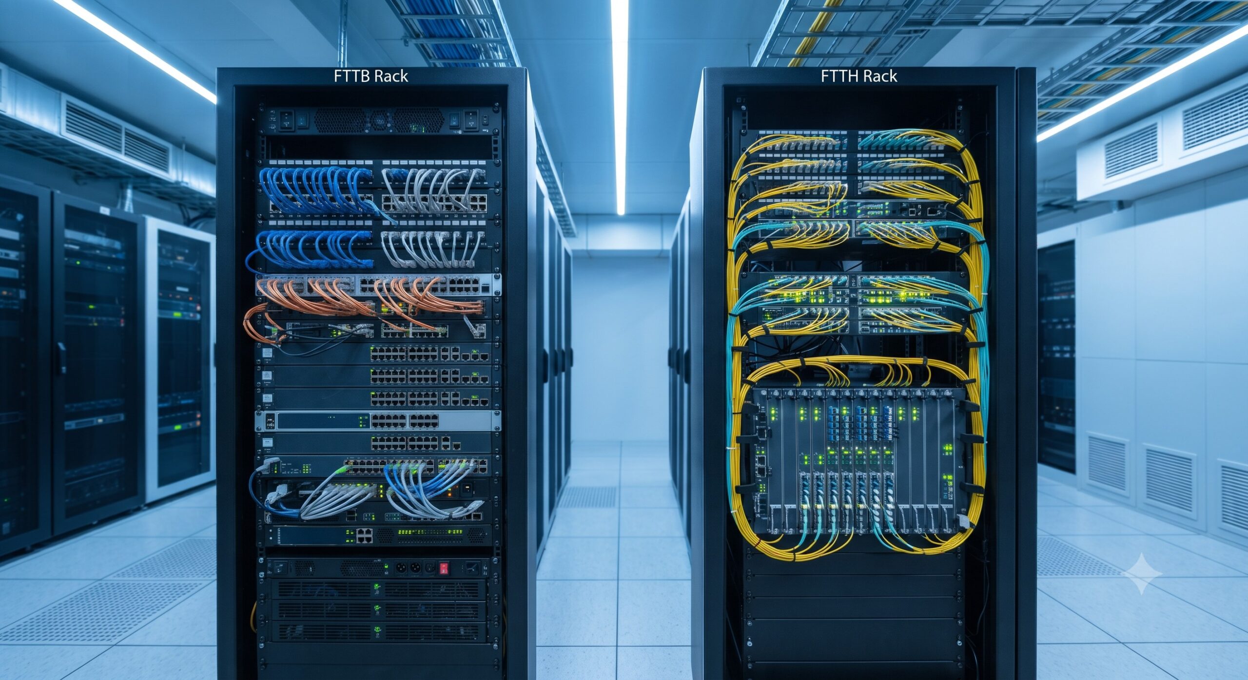
The TCO comparison between FTTB and FTTH extends beyond simple per-subscriber equipment costs. In an FTTB architecture, the Optical Line Terminal (OLT) is housed at the central office, and the fiber is terminated at a Multi-Dwelling Unit (MDU) or business complex. The active switching and VDSL/GPON ONT (Optical Network Terminal) equipment must be powered, cooled, and maintained within the building’s telecom room. This introduces significant operational expenditures (OPEX) including electricity costs, battery backup maintenance, and lease agreements for space. Conversely, an FTTH architecture pushes the fiber directly to the subscriber premises, eliminating the active intermediate node. The passive optical splitter requires no power or cooling. While the initial Civil Works (digging and fiber laying) CAPEX for FTTH is substantially higher, the elimination of active building-level electronics yields a recurring OPEX saving of 40-60% over a 10-year lifecycle. For high-density urban areas, the long-term savings on power alone often justify the infrastructure investment.
SCALABILITY ADVANTAGES
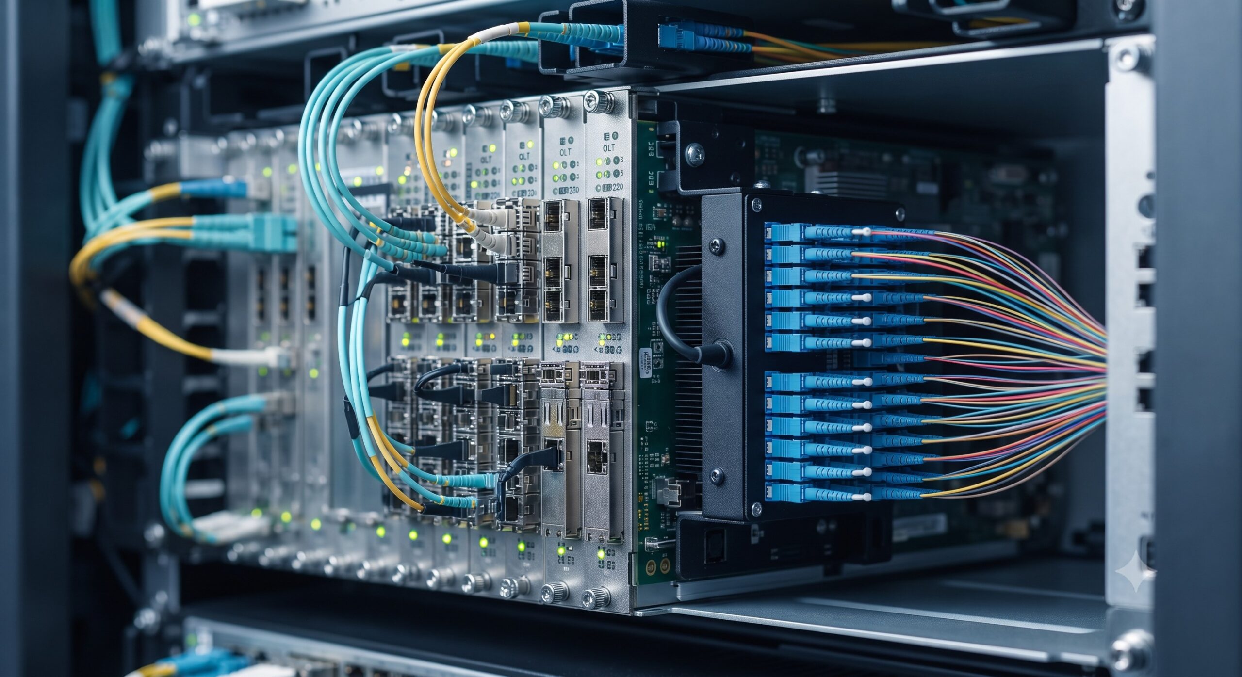
Scalability is a critical strategic dimension where FTTH demonstrates unparalleled superiority. FTTB networks are typically constrained by the capacity of the copper last-mile (VDSL2 or G.fast), offering maximum aggregated bandwidth of 100 Mbps to 1 Gbps per building, shared among all residents. This bottleneck limits the ability to offer future services like 4K/8K streaming, cloud computing, and VR applications. FTTH, based on XGS-PON or 25G-PON standards, provides a future-proof symmetric bandwidth of 10 Gbps to 25 Gbps per optical port, with the physical medium capable of supporting future terabit-class upgrades. From a hardware procurement perspective, investing in an OLT chassis with high-density 10G/25G optical interfaces and pluggable optics (e.g., SFP-10G-D, SFP-28-D) ensures the aggregation layer remains non-blocking. The Central Office hardware is fully leveraged across hundreds of subscribers, improving the CAPEX efficiency ratio. While individual ONTs for FTTB MDUs can be shared, each requires individual Active Ethernet or P2MP management, which complicates network operations. FTTH simplifies this by providing a single, direct logical link to the subscriber, enabling finer SLA (Service Level Agreement) management and rapid service provisioning.
SPECIFICATION REPORT
This section encapsulates the critical hardware specifications for network elements pivotal to both architectures. The data informs the strategic decision regarding which equipment to procure.
FTTB Architecture (Central Office & Building Nodes):
– Central Office OLT: 10U Chassis, 1.2 Tbps switching capacity, 10G uplink ports, -48V DC / 110-240V AC redundant power supplies.
– MDU Distribution Switch: 1U compact switch, 24x 1G RJ45 ports, 2x 10G SFP+ uplinks, Power over Ethernet (PoE) capability for in-building distribution.
– Building ONT: Wall-mountable unit, 4x Gigabit Ethernet ports, 2x RJ11 POTS ports, 2×4 2.4GHz WiFi, supported by local AC-DC adapter.
FTTH Architecture (Central Office & Subscriber Nodes):
– Central Office OLT (Next-Gen): 5U Chassis, non-blocking 3.6 Tbps fabric, 16x 25G SFP28 ports for 25G-PON, integrated Layer 3 routing.
– FTTH Optical Splitter (Passive): 1:64 or 1:128 ratio, housed in an outdoor closure with IP67 protection.
– Subscriber ONT (Home Gateway): Compact desktop design, 1x G/EPON or XGS-PON port, 4x Gigabit Ethernet ports, 1x USB 3.0, 2×2 5GHz WiFi 6, low-power idle (sub 5W).
| Parameter | FTTB (Metro/Urban) | FTTH (Metro/Urban) |
|---|---|---|
| Initial CAPEX per Subscriber | Low (USD 300 – 500) | High (USD 800 – 1500) |
| Recurring OPEX (Power/Cooling) | High (Active Node in MDU) | Low (Passive Splitting) |
| Physical Medium | Fiber + Copper (VDSL/G.fast) | End-to-End Fiber (ITU-T G.652) |
| Max Bandwidth (Shared) | 100 Mbps – 1 Gbps (per building) | 2.5 Gbps – 10 Gbps (per subscriber) |
| Active Equipment per Node | Switch + ONT + PSU + Backup Battery | Passive Splitter only (100% passive) |
| MTBF (Mean Time Between Failures) | 25,000 Hours (Active Electronics) | > 500,000 Hours (Passive Plant) |
| Scalability to 25G/50G | Requires complete overhaul | Fiber-ready. Upgrade optics/OLT only |
| Network Management Complexity | High (multiple active CPEs) | Low (direct logical connection) |
FINAL MAIN HEADING
SAFETY CERTIFICATIONS
Both FTTB and FTTH hardware must adhere to rigorous international safety and environmental standards to guarantee operational integrity. For central office and MDU equipment, the following certifications are mandated: IEC 62368-1 for audio/video and ICT equipment safety, GR-1089-CORE for electromagnetic compatibility and electrical safety in telecom environments, and NEBS Level 3 for network equipment-building system compliance, ensuring resistance to temperature, fire, and seismic activity. The passive optical splitters and outdoor distribution frames (ODFs) require IP ratings (IP65/IP67) and meet GR-326-CORE for optical connector reliability. For subscriber-premise equipment (ONTs), key certifications include FCC Part 15B for EMI, UL/CSA 60950-1/62368-1 for safety, and RoHS/REACH for environmental compliance. The power adapters must be Energy Star Level VI compliant to minimize idle power consumption. This stringent compliance matrix ensures zero operational downtime and offers a defensible procurement position against liability and regulatory audits.
VISUAL DEPLOYMENT SUMMARY
A comparative network topology is essential for visualizing the cost drivers. In an FTTB deployment, multiple fiber strands from the OLT feed into an MDU, connecting to a field-switch or ONT that converts optical to electrical signals. This signal is then distributed via copper CAT5/6 cabling within the building’s riser closet, requiring intermediate distribution frames (IDFs). The OPEX accrues via air conditioning to cool the IDF closet and power backup for the switch. In contrast, the FTTH deployment employs a centralized OLT with high-density fiber terminations. A single fiber runs to a passive optical splitter located in a street cabinet. This splitter divides the signal, and individual fibers traverse directly into each subscriber’s home, connecting to a simple, low-power ONT. The visual summary highlights the elimination of all active electronics between the central office and the living room, providing a leaner, more reliable network. For network planners, this schematic underscores the strategic imperative to invest in robust OLT hardware with high-port density and long-reach optics, effectively centralizing costs and power, while relying on scalable, low-maintenance passive optical distribution networks.
📥 Download Technical Specification
Click the button below to view or download the full official PDF datasheet.

Leave a comment