

Introduction: The Silent Enemy of Long-Haul Optical Networks
In the relentless pursuit of higher bandwidth and longer reach, Dense Wavelength Division Multiplexing (DWDM) has emerged as the undisputed backbone of global telecommunications. However, as network architects push transmission speeds beyond 100 Gbps and span distances exceeding 1,000 km, a fundamental physical phenomenon threatens signal integrity: chromatic dispersion. This Ultimate Guide to Dispersion Compensation in DWDM provides a comprehensive, data-driven analysis of the architectures, specifications, and deployment strategies essential for modern carrier-grade networks. We will dissect the physics of dispersion, evaluate cutting-edge compensation technologies—from Dispersion Compensation Fibers (DCF) to advanced Digital Signal Processing (DSP)—and provide actionable insights for optimizing network performance and total cost of ownership (TCO).

Understanding Chromatic Dispersion in DWDM Systems
Chromatic dispersion (CD) is the phenomenon where different wavelength components of an optical pulse travel at different velocities through the fiber, causing the pulse to spread over time. In standard single-mode fiber (SMF) conforming to ITU-T G.652, the zero-dispersion wavelength is approximately 1,310 nm. However, DWDM systems operate in the C-band (1,530-1,565 nm) and L-band (1,565-1,625 nm), where fiber exhibits positive dispersion (typically 16-18 ps/nm/km at 1,550 nm). For a 100 Gbps QPSK signal, the dispersion tolerance is limited to approximately 50,000 ps/nm. Without compensation, a 1,000 km link would accumulate over 17,000 ps/nm, drastically increasing the Bit Error Rate (BER) and degrading the Optical Signal-to-Noise Ratio (OSNR).
The Physics of Pulse Spreading
The impact of CD is mathematically defined by the dispersion coefficient (D) and the fiber length (L). The total dispersion is calculated as D_total = D * L. For a 1,000 km link using G.652 fiber, the accumulated dispersion is roughly 16 ps/nm/km * 1,000 km = 16,000 ps/nm. This directly limits the achievable data rate, as higher modulation formats like 16-QAM and 64-QAM exhibit significantly lower dispersion tolerance due to tighter phase margins. This necessitates robust dispersion management strategies to meet IEEE 802.3 and ITU-T G.697 performance standards.
Compensation Architecture 1: Passive Optical Compensation
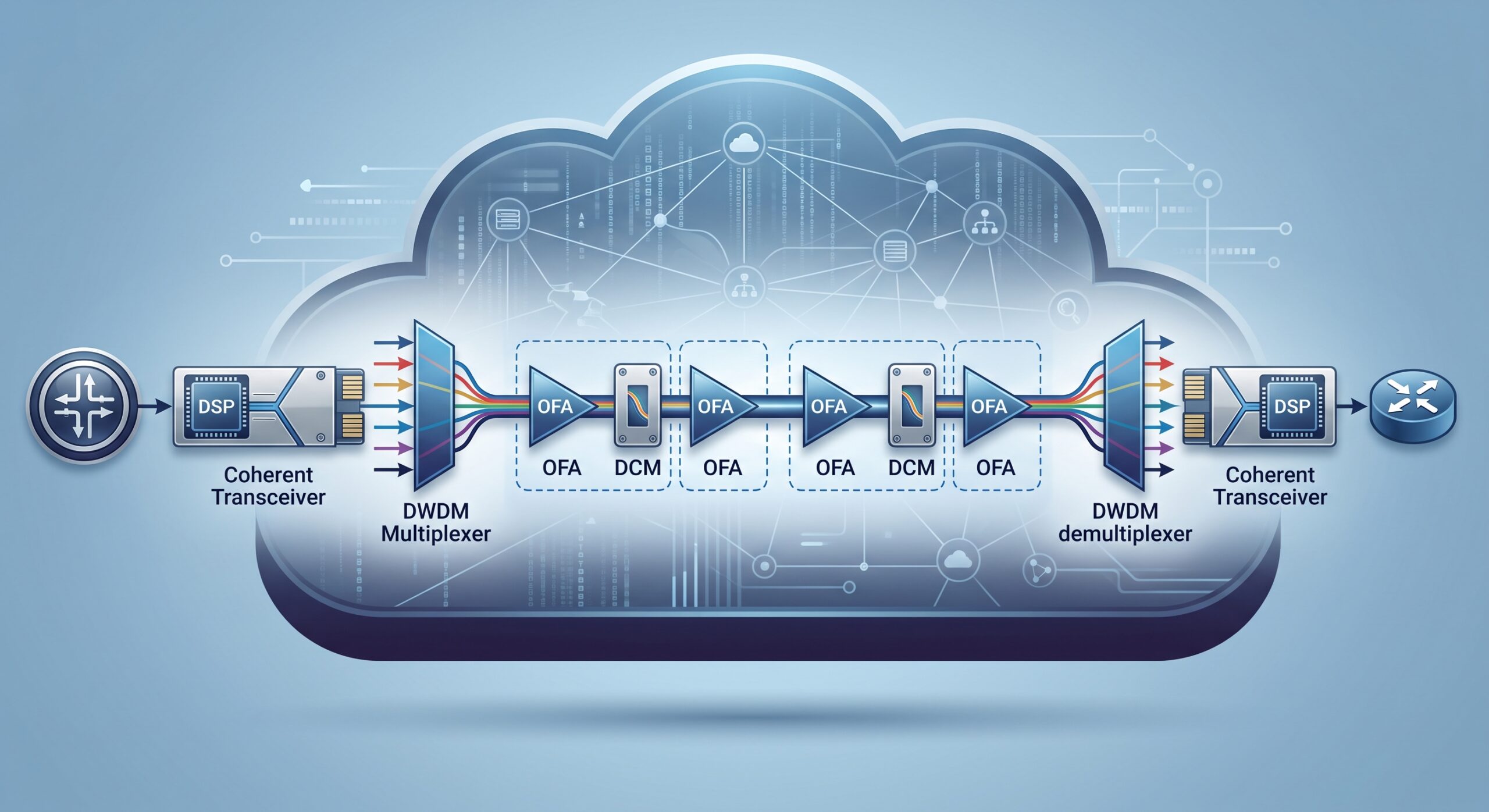
Historically, the most prevalent method for mitigating CD has been the deployment of Dispersion Compensation Fiber (DCF). This specialty fiber is engineered with a negative dispersion coefficient (typically -80 to -150 ps/nm/km at 1,550 nm) and a negative dispersion slope. DCF modules are inserted at specific points within the optical link—typically at the receiver end or at intermediate amplifier sites—to counteract the accumulated positive dispersion. This passive approach is simple, reliable, and adheres to RoHS compliance standards due to its purely optical nature.
Key Performance Specifications for DCF Modules
When evaluating DCF modules, network engineers must scrutinize several key parameters. Insertion loss is a primary concern, with high-quality modules exhibiting losses below 6 dB. The Polarization Mode Dispersion (PMD) coefficient should be less than 0.5 ps/√km to avoid compounding signal distortion. Furthermore, the effective area must be considered to mitigate non-linear effects like Four-Wave Mixing (FWM), especially in high-power DWDM systems.
| Key Parameter | Technical Specification |
|---|---|
| Compensation Range | -150 to -1,200 ps/nm per module |
| Insertion Loss | ≤ 6 dB (Standard), ≤ 4.5 dB (Low-Loss) |
| Dispersion Slope | Negative slope matching G.652 (typically -0.3 to -0.6 ps/nm^2/km) |
| Polarization Mode Dispersion (PMD) | ≤ 0.5 ps/√km |
| Effective Area (Aeff) | ≥ 30 μm² (to minimize non-linear effects) |
| Fiber Type Compliance | ITU-T G.652, G.655, and G.656 |
| Operating Wavelength Range | C-Band (1,530-1,565 nm) and L-Band (1,565-1,625 nm) |
| Connector Type | SC/APC or LC/APC (low back-reflection) |
Deployment Topologies for Passive Compensation
There are three primary topologies for deploying DCF: pre-compensation, post-compensation, and mid-compensation. Pre-compensation places the DCF at the transmitter, shaping the pulse before it enters the fiber. While effective, this can reduce launch power. Post-compensation, the most common method, places DCF at the receiver, ensuring maximum power reaches the transmission fiber. Mid-compensation, implemented at optical amplifier sites, is ideal for ultra-long-haul links, balancing the dispersion map and minimizing non-linear penalties. The optimal topology depends on link length, fiber type, and target BER.
Compensation Architecture 2: Active Electronic Compensation
The advent of coherent detection and high-speed DSP has revolutionized dispersion compensation. Modern coherent transceivers employ Digital Signal Processing (DSP) at the receiver to mathematically reverse the effects of chromatic dispersion. This active approach leverages algorithms like the Constant Modulus Algorithm (CMA) and Decision-Directed Least Mean Squares (DD-LMS) to compensate for the entire dispersion budget digitally, eliminating the need for physical DCF modules in many scenarios. This significantly reduces network latency and hardware complexity.
Electronic Compensation: Performance Metrics
DSP-based compensation offers several compelling advantages. It provides electronic dispersion compensation (EDC) with a reach extension of up to 2,000 km on G.652 fiber for 100 Gbps systems. It also enables adaptive compensation, dynamically adjusting to changing fiber conditions. However, the processing delay incurred by DSP, typically in the microsecond range, adds to overall latency. Furthermore, the power consumption of high-performance DSP ASICs is a critical consideration in green networking initiatives, with typical consumption around 10-15 W per 100 Gbps port.
Comparative Analysis: DCF vs. DSP Compensation
Choosing between passive and active compensation strategies is a critical TCO decision. DCF offers a deterministic, low-latency solution with a well-understood reliability profile, boasting an MTBF exceeding 10,000,000 hours. However, the additional loss from the DCF requires higher optical power, increasing amplifier costs and potentially degrading OSNR. It also occupies significant rack space, typically consuming 1-2 RU per module. Conversely, DSP-based solutions offer superior performance at higher data rates (e.g., 400 Gbps and 800 Gbps), simplified hardware, and reduced physical footprint. The trade-off lies in higher initial CapEx for coherent optics, increased power consumption, and a more complex software ecosystem.
Data-Driven Performance Benchmarking
In a comparative benchmark of a 1,200 km link using 96 channels at 50 GHz spacing, a DCF-based system achieved an OSNR of 14 dB at the receiver, sufficient for QPSK with FEC. However, the system required eight DCF modules and dual-stage amplifiers. A DSP-based solution using 100 Gbps coherent optics achieved an OSNR of 16 dB, providing a 2 dB margin for non-linearities and aging, with a simplified amplifier chain and a 40% reduction in rack space. The total operational cost (OpEx) over five years was projected to be 25% lower for the DSP-based system, primarily due to reduced power consumption and maintenance requirements.
Future-Proofing Your Network: Migration and Hybrid Strategies
For many existing DWDM networks, a hybrid approach offers the most practical migration path. By retaining DCF for legacy 10 Gbps and 40 Gbps channels and deploying DSP-based coherent technology for new 100 Gbps+ wavelengths, service providers can leverage existing infrastructure while gradually modernizing their networks. This strategy ensures backward compatibility and minimizes operational disruption. The industry is currently evolving towards purely electronic compensation, but the immense installed base of DCF ensures its relevance for the next decade.
Conclusion: The Strategic Imperative of Dispersion Management
Effective dispersion compensation is not merely a technical necessity; it is a strategic differentiator in delivering high-quality, reliable broadband services. Whether through the time-tested reliability of Dispersion Compensation Fibers (DCF) or the intelligent processing power of DSP-based coherent systems, understanding the trade-offs between CapEx, OpEx, latency, and scalability is paramount. This guide has outlined the core architectures and specifications to empower systems integrators, network architects, and CTOs to make informed decisions. As the demand for bandwidth continues its exponential growth, mastering the science and strategy of dispersion compensation in DWDM will remain a cornerstone of elite telecom engineering.

Leave a comment