
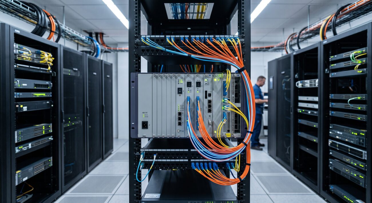
Introduction: The Unseen Pillar of Network Uptime
In the demanding landscape of telecommunications, network architects and systems integrators often focus on routing capacity and throughput. However, the consistent, reliable operation of any network node is fundamentally dependent on a robust power architecture. For carriers adhering to five-nines (99.999%) availability standards, the ZTE Power Subrack is not merely an accessory; it is a critical component engineered for high resilience. This article offers a carrier-grade technical deep dive into the ZTE Power Subrack configuration, examining its fault-tolerant architecture, redundancy mechanisms, and the technical specifications that underpin its reliability in mission-critical environments.
Architectural Overview: The 19-Inch Standard
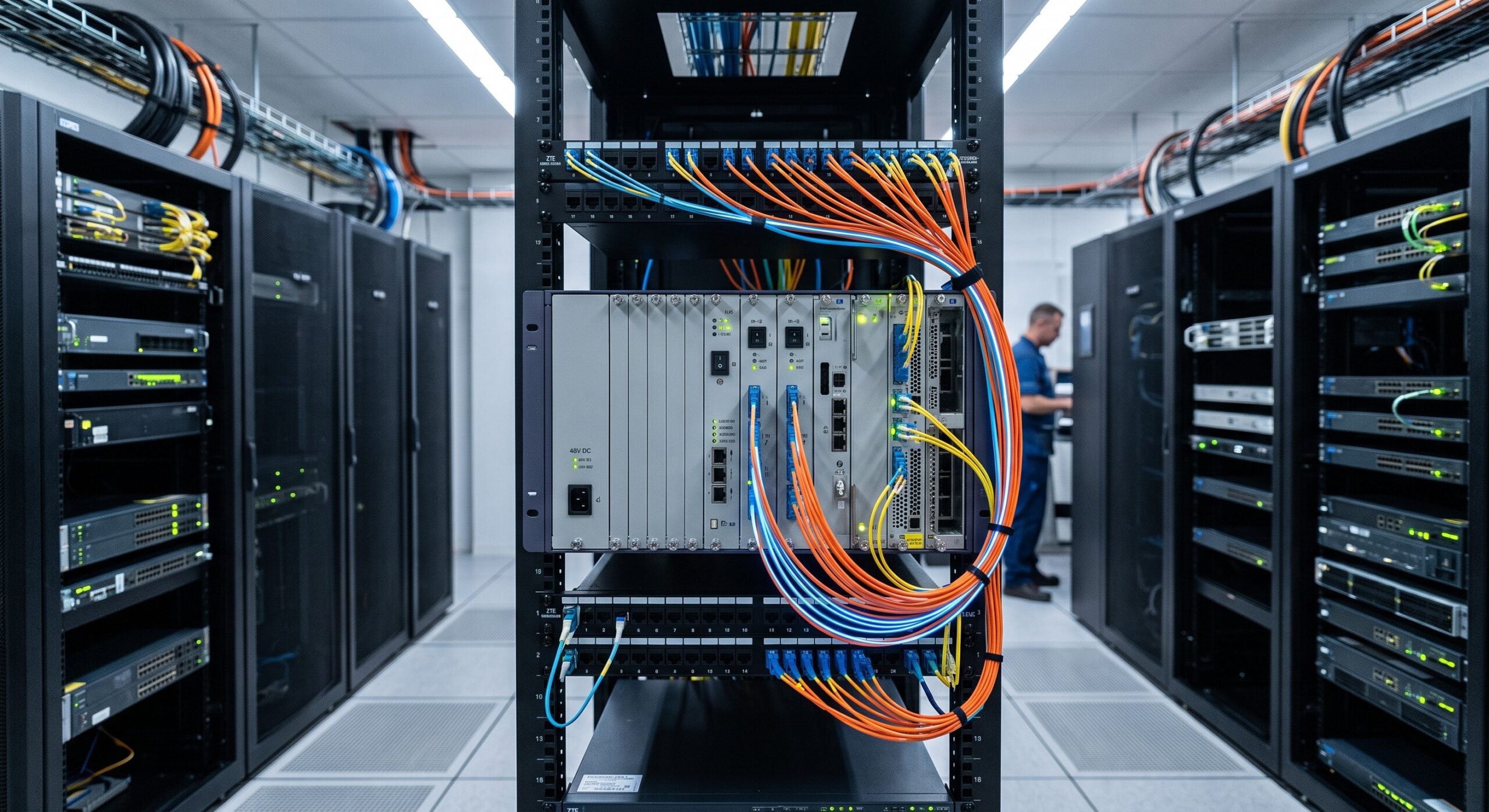
Modern ZTE power subracks, such as the ZXDU48 B600 and ZXDU68 B301 series, adhere to the industry-standard 19-inch rack mount form factor. Height configurations typically range from 1U to 6U, allowing for flexible integration into existing central office and datacenter infrastructure. The subrack serves as the central hub for power distribution, housing key units within a standardized chassis designed for optimal thermal management and ease of maintenance.
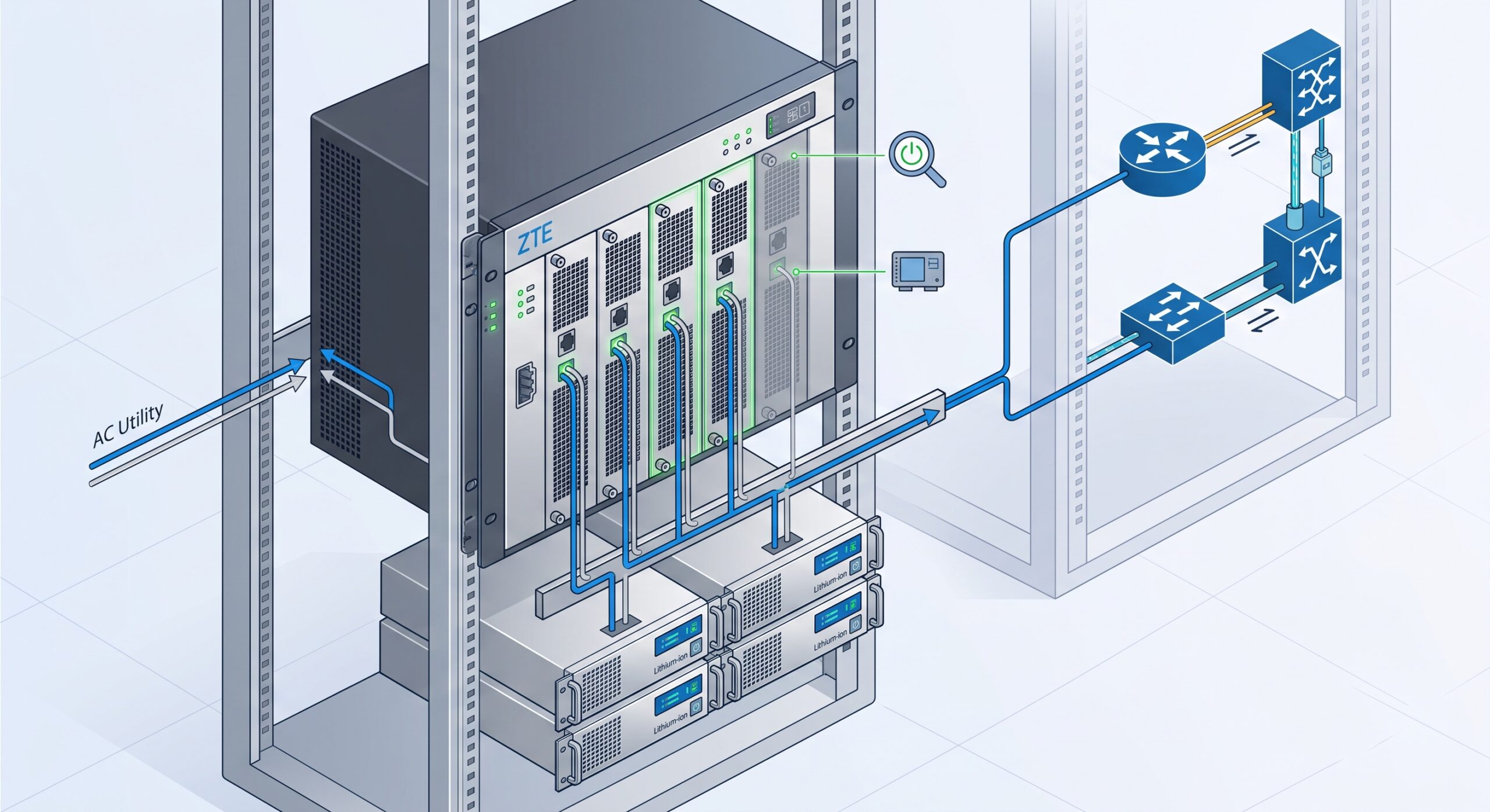
At its core, the subrack consolidates AC/DC conversion and distribution into a single, manageable unit. The composition generally includes an AC distribution unit, a DC distribution unit, high-efficiency rectifier modules, and a Centralized Supervision Unit (CSU). This integrated design reduces cabling complexity and physical footprint, a key advantage in space-constrained environments .
Key Physical Specifications
The physical design of the ZTE subrack is a critical factor in its suitability for high-density deployments. For example, the ZXDU68 B301 system delivers an impressive 18kW output power within its 6U, 19-inch chassis, demonstrating a high power density that is essential for powering multiple baseband and RF units from a single point . The standard dimensions and weight, such as the 25kg of the B301 model, reflect the robust construction required to support high-current busbars and ensure mechanical stability .
Installation guidelines from ZTE, particularly for embedded systems like the 1U ZXDU48 B600, emphasize the importance of physical spacing for thermal dissipation. Rear cabinet doors require a minimum clearance of 50 mm if ventilated, and up to 80 mm if not, ensuring forced-air cooling systems can effectively manage the thermal load of the rectifiers .
Deep Dive: Core Components and High-Availability Architecture
Carrier-grade reliability is achieved through the intelligent integration of high-efficiency modules and a sophisticated control plane. The subrack’s architecture is designed to eliminate single points of failure through component redundancy and hot-swappable functionality.
1. Centralized Supervision Unit (CSU)
The CSU functions as the brain of the power system, providing comprehensive monitoring and management. It continuously tracks the operational status of all components, manages battery charging and discharging cycles, and implements intelligent control features like rectifier sleep mode to enhance energy efficiency . The CSU provides critical networking interfaces, such as RS232, RS485, and Ethernet (FE), allowing for remote management and integration with Network Management Systems (NMS) .
From a fault tolerance perspective, the CSU manages sophisticated alarm systems via input/output dry contacts. In the event of a component failure or deviation from operational thresholds (e.g., undervoltage), the CSU can trigger immediate alarms and, in some configurations, initiate protective actions, contributing directly to system Mean Time Between Failures (MTBF).
2. Power Distribution Unit (PDU)
The PDU is the physical hub for power routing, distributing the converted DC power to the connected telecom load equipment. It provides multiple output branches, often with circuit breakers or fuses for individual load protection. For instance, some subracks feature dedicated Load 1 and Load 2 terminals, with a total current capacity of 30A, and battery terminals for float charging operations .
3. Rectifier Modules
The rectifier modules are the heart of the power conversion process. ZTE’s modern rectifiers, such as the ZXD3000v5.5 and R4875F1, are rated for peak efficiencies exceeding 96%, which directly reduces operational expenses and thermal dissipation . These modules operate in a hot-swappable, N+1 or N+N redundant configuration. If one rectifier fails, the load is automatically balanced across the remaining operational units, ensuring uninterrupted power delivery. Furthermore, the system can operate within a wide input voltage range (85V~300V AC), providing stability against unstable grid conditions .
| Key Parameter | Technical Specification | Benefit for Carrier-Grade Ops |
|---|---|---|
| Peak Rectifier Efficiency | 96% – 97% | Reduces OpEx and thermal load, improves MTBF |
| N+1 Redundancy | Hot-Swappable Modules | Zero downtime during module failure or maintenance |
| Wide Input Voltage Range | 85V ~ 300V AC | Protects against grid instability; ensures system stability |
| Compliance Standards | IEC 62368, IEC 61000, EN 55032 | Ensures safety and EMC compliance for global deployment |
| System Output Power | Up to 24kW | Supports high-density configurations |
Data-Driven Reliability: Key Technical Specifications
For a telecom hardware evaluator, quantifiable metrics are paramount. The following table synthesizes critical specifications from various ZTE power subrack models, illustrating the parameters that define their carrier-grade performance.
Redundancy and Fault Tolerance in Practice
The configuration of the ZTE Power Subrack is fundamentally about eliminating single points of failure. In a typical deployment, the power subrack is configured to meet specific carrier SLAs.
N+1 Rectifier Redundancy
In a high-availability configuration, an extra rectifier module is installed beyond what is needed to support the full load. This N+1 redundancy ensures that the system can continue to operate at full capacity even if one rectifier fails. This architecture is essential for maintaining MTBF and system availability during maintenance or unexpected hardware issues.
Backup Battery Integration
The power subrack is designed to interface with external battery banks. The DC distribution unit includes terminals for connecting the battery pack, allowing the CSU to manage battery charging and health. In case of an AC mains failure, the system seamlessly switches to battery power, providing a reliable backup power source to ensure the telecom equipment remains operational.
Compliance and Safety
From a safety and standards standpoint, ZTE power subracks comply with critical international regulations. Systems like the ZXDUPA-CR01 are certified to meet IEC 62368 for safety and IEC 61000, EN 55032 for electromagnetic compatibility (EMC). Additionally, the integration of surge protection devices ensures compliance with telecom-grade lightning protection standards, safeguarding valuable downstream equipment .
Conclusion: The Strategic Value of a Robust Power Foundation
The ZTE Power Subrack Configuration is a sophisticated engineering solution that transcends simple power supply functions. It embodies a strategic approach to network reliability, integrating high-efficiency rectification, intelligent control, and comprehensive redundancy into a modular platform. For network architects and engineers, understanding the architecture and spec sheets—from the 96% efficiency of the rectifiers to the hot-swappable N+1 redundancy—is essential for designing a network that delivers the carrier-grade uptime demanded by modern digital services.
By investing in a robust power subrack architecture, operators ensure their core network hardware receives clean, reliable power, thereby maximizing infrastructure ROI and minimizing downtime risks associated with power fluctuations and component failures.

Leave a comment