

EXECUTIVE SUMMARY
This document serves as the definitive technical reference for the Low Voltage Disconnect (LVD) configuration manual, a critical hardware subsystem engineered to safeguard telecommunications and datacenter power infrastructures. The LVD module provides automated, intelligent load shedding to protect battery banks from deep discharge, thereby extending battery life and ensuring system availability. Designed for integration into -48 VDC and +24 VDC power distribution systems, this manual details the comprehensive hardware specifications, operational logic, configuration parameters, and compliance standards. The LVD solution delivers a robust mechanism for priority-based load disconnection, ensuring that essential networking equipment remains operational during prolonged mains failures, a fundamental requirement for carrier-grade network availability.

ARCHITECTURE & CHASSIS DESIGN
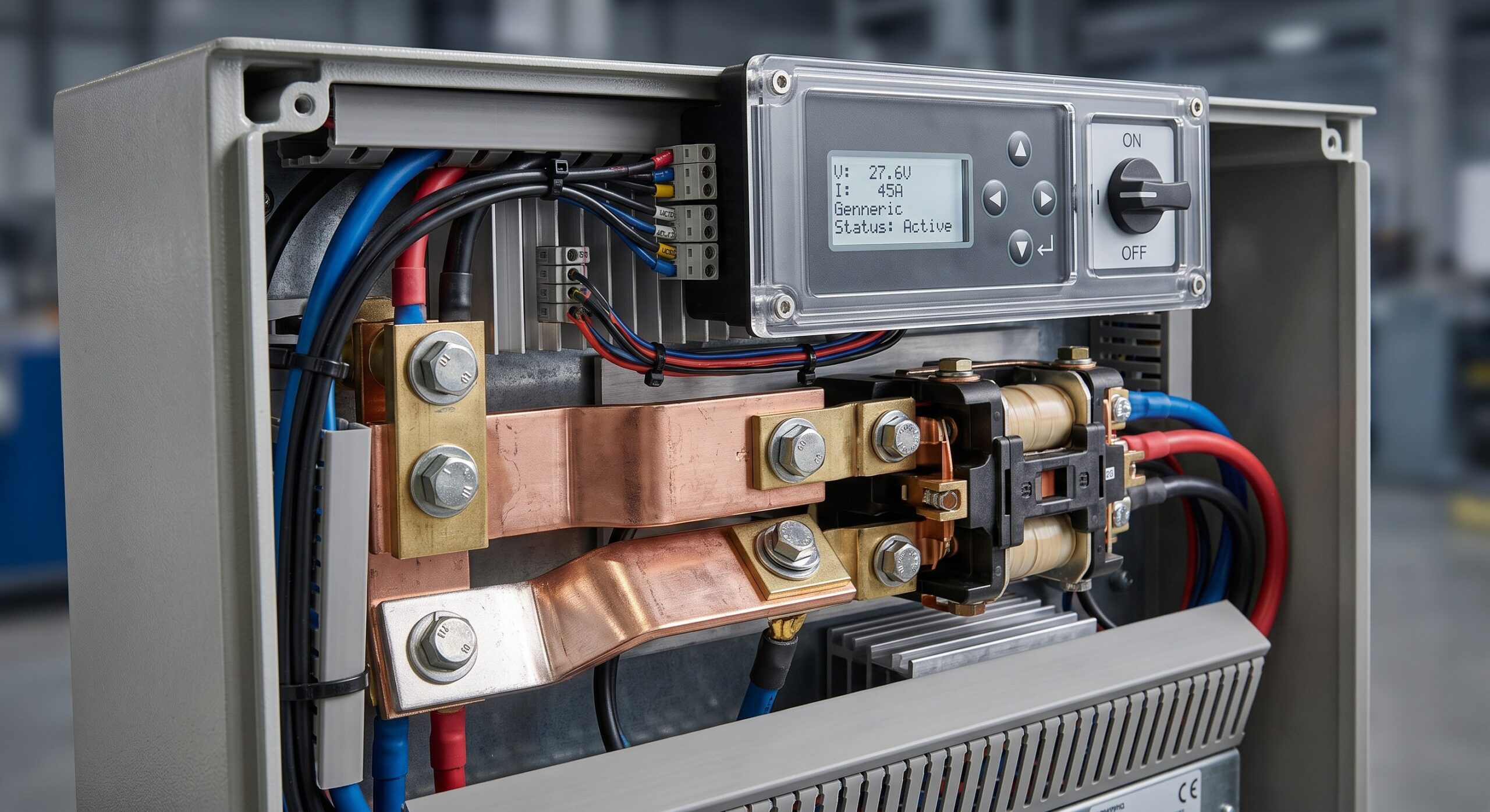
The LVD module is architected as a high-current, low-resistance switching system with a microcontroller-based control plane. The chassis is a compact, ruggedized 1RU enclosure designed for standard 19-inch or ETSI rack mounting. The hardware topology comprises a main current path with high-performance MOSFET switching arrays, a dedicated sense circuit for voltage and current monitoring, and a galvanically isolated control interface. The design prioritizes a near-zero voltage drop across the disconnect path to maximize power efficiency and minimize heat dissipation. The front panel features a clear LED status matrix indicating operational state, alarm conditions, and the configured disconnect voltage thresholds. The rear panel hosts the primary power input and output busbars, along with a DB-9 serial console port for local configuration and an RJ-45 port for network-based remote management via SNMP or Modbus protocols. The internal backplane provides a segregated path for high-current power and low-voltage control signals, ensuring electromagnetic interference (EMI) shielding and signal integrity.
HARDWARE FEATURES
– AUTOMATIC LOW VOLTAGE DISCONNECT: Precisely monitors DC bus voltage and disconnects non-critical load banks when voltage drops below user-configurable thresholds (e.g., 42V for 48V systems).
– PRIORITY-BASED LOAD SHEDDING: Supports two or more independent load disconnect channels, allowing administrators to define critical and non-critical loads, ensuring power is preserved for essential routing, switching, and transmission equipment.
– HYSTERESIS AND RE-CONNECT LOGIC: Features programmable hysteresis to prevent relay or MOSFET chatter. Automatic re-connection occurs when the primary power source is restored and the battery voltage has recovered to a safe level (e.g., > 48V).
– MANUAL BYPASS: A physical lockable bypass switch is provided for maintenance and emergency scenarios, allowing operators to manually override the disconnect state.
– COMPREHENSIVE TELEMETRY: Built-in monitoring for voltage, current, and temperature on each load channel. Data is logged locally and can be streamed to a central network management system (NMS).
– ALARM & EVENT NOTIFICATION: Configurable dry contact relays and SNMP traps provide immediate notification of disconnect events, threshold breaches, and device faults.
– HOT-SWAPPABLE CONTROL LOGIC: The control board is a modular, field-replaceable unit (FRU), enabling firmware upgrades and maintenance without disrupting the power path.
COMPLIANCE & STANDARDS
The LVD hardware subsystem is designed and validated to meet the rigorous standards of the global telecommunications industry. It complies with the safety requirements of IEC 60950-1 and IEC 62368-1 for audio/video and information technology equipment. The EMC performance is fully compliant with EN 55032 (Class A) and EN 55024, ensuring operation in commercial and industrial electromagnetic environments without interference. For electrical safety, the unit meets UL 60950-1 and CSA C22.2 No. 60950-1. Additionally, the design adheres to the operational standards for network equipment building systems (NEBS) for thermal, vibration, and airborne contaminant resistance. All components are compliant with the Restriction of Hazardous Substances (RoHS) and Registration, Evaluation, Authorisation and Restriction of Chemicals (REACH) directives, ensuring a sustainable and environmentally responsible product lifecycle.
TECHNICAL SPECIFICATIONS
– SYSTEM INPUT VOLTAGE RANGE: -36 VDC to -60 VDC (Nominal -48 VDC) or +18 VDC to +30 VDC (Nominal +24 VDC)
– MAXIMUM CONTINUOUS CURRENT PER CHANNEL: 100 A / 200 A (depending on model configuration)
– NUMBER OF LOAD CHANNELS: 2 (Priority A – Critical; Priority B – Non-Critical)
– DISCONNECT VOLTAGE THRESHOLD: Field programmable (e.g., 40.0 VDC to 44.0 VDC for 48V systems)
– RECONNECT VOLTAGE THRESHOLD: Field programmable (e.g., 46.0 VDC to 50.0 VDC for 48V systems)
– VOLTAGE MEASUREMENT ACCURACY: ± 0.5% of reading
– CURRENT MEASUREMENT ACCURACY: ± 1.0% of reading
– OPERATING TEMPERATURE RANGE: -5°C to +55°C
– STORAGE TEMPERATURE RANGE: -40°C to +85°C
– RELATIVE HUMIDITY: 5% to 95% (non-condensing)
– CONTROL INTERFACE: 10/100BASE-T Ethernet (SNMPv2c/v3, Modbus TCP), RS-232 Serial (DB-9)
– STATUS INDICATORS: LEDs for Power, Alarm, Status per Channel
– FORM FACTOR: 1RU, 19-inch rack mountable (depth 250mm)
– WEIGHT: 2.5 kg (5.5 lbs)
– MTBF (TELCORDIA SR-332): > 500,000 hours
| Parameter | Specification |
|---|---|
| Form Factor | 1RU 19-inch Rackmount Chassis |
| Switching Capacity | 200A / 400A Total (Model Dependent) |
| Power Supply | 1+0 Integrated, -48 VDC / +24 VDC Systems |
| Disconnect Threshold | Programmable: 40.0V to 44.0V (-48V systems) |
| Reconnect Threshold | Programmable: 46.0V to 50.0V (-48V systems) |
| Control Interface | 10/100BASE-T (SNMP/Modbus), RS-232 Serial |
| Operating Temperature | -5°C to +55°C |
| Compliance | IEC 60950-1, EN 55032, UL 60950-1, NEBS Level 3 |
| MTBF | > 500,000 hours (Telcordia SR-332) |
ORDERING OPTIONS
The LVD subsystem is offered in a variety of factory-configured models to match specific capacity, control, and interface requirements. Standard ordering options are detailed in the table below. All configurations include the base chassis, control unit, and installation hardware. Optional accessories such as extended front bezels, cable management kits, and redundant control modules are also available. For custom configurations requiring specific voltage thresholds or contact ratings, please contact the OEM Sales Engineering team for a tailored solution and a formal quotation.
| ORDERING CODE | MODEL DESCRIPTION | CHANNEL CAPACITY | INPUT VOLTAGE | INTERFACE |
| :— | :— | :— | :— | :— |
| LVD-200-48C | Standard LVD Module, 200A total capacity | 2 x 100A | -48 VDC | Ethernet & Serial |
| LVD-400-48H | High-Capacity LVD Module, 400A total capacity | 2 x 200A | -48 VDC | Ethernet & Serial |
| LVD-100-24C | Standard LVD Module, 100A total capacity | 2 x 50A | +24 VDC | Ethernet & Serial |
| LVD-200-24H | High-Capacity LVD Module, 200A total capacity | 2 x 100A | +24 VDC | Ethernet & Serial |
| LVD-200-48C-R | LVD Module with Redundant Control Board | 2 x 100A | -48 VDC | Ethernet & Serial |
📥 Download Technical Specification
Click the button below to view or download the full official PDF datasheet.

Leave a comment