

PRODUCT IDENTIFICATION
The Cold Plate Liquid Cooling Module System is a carrier-grade thermal management subsystem engineered for high-density telecom compute and switching environments. This technical reference manual provides a complete component-level breakdown of the liquid cooling loop, cold plate assemblies, coolant distribution infrastructure, and control electronics. The system is designed to dissipate thermal loads exceeding 1,200 W per node while maintaining junction temperatures within ASIC and FPGA manufacturer tolerances. Each module is qualified for continuous operation in central office and edge data center environments, supporting direct-to-chip cooling for next-generation routing, optical transport, and packet core platforms.
The architecture comprises six principal functional blocks: the Cold Plate Assembly, the Coolant Distribution Unit (CDU), the Secondary Loop Manifold Network, the Quick-Disconnect Coupling Interface, the Leak Detection and Monitoring Subsystem, and the Thermal Control Firmware Module. This document details the mechanical, electrical, and fluidic specifications for each block, enabling systems engineers to integrate the module into existing 19-inch or 21-inch rack infrastructure with minimal facility modification.

SYSTEM HARDWARE TOPOLOGY
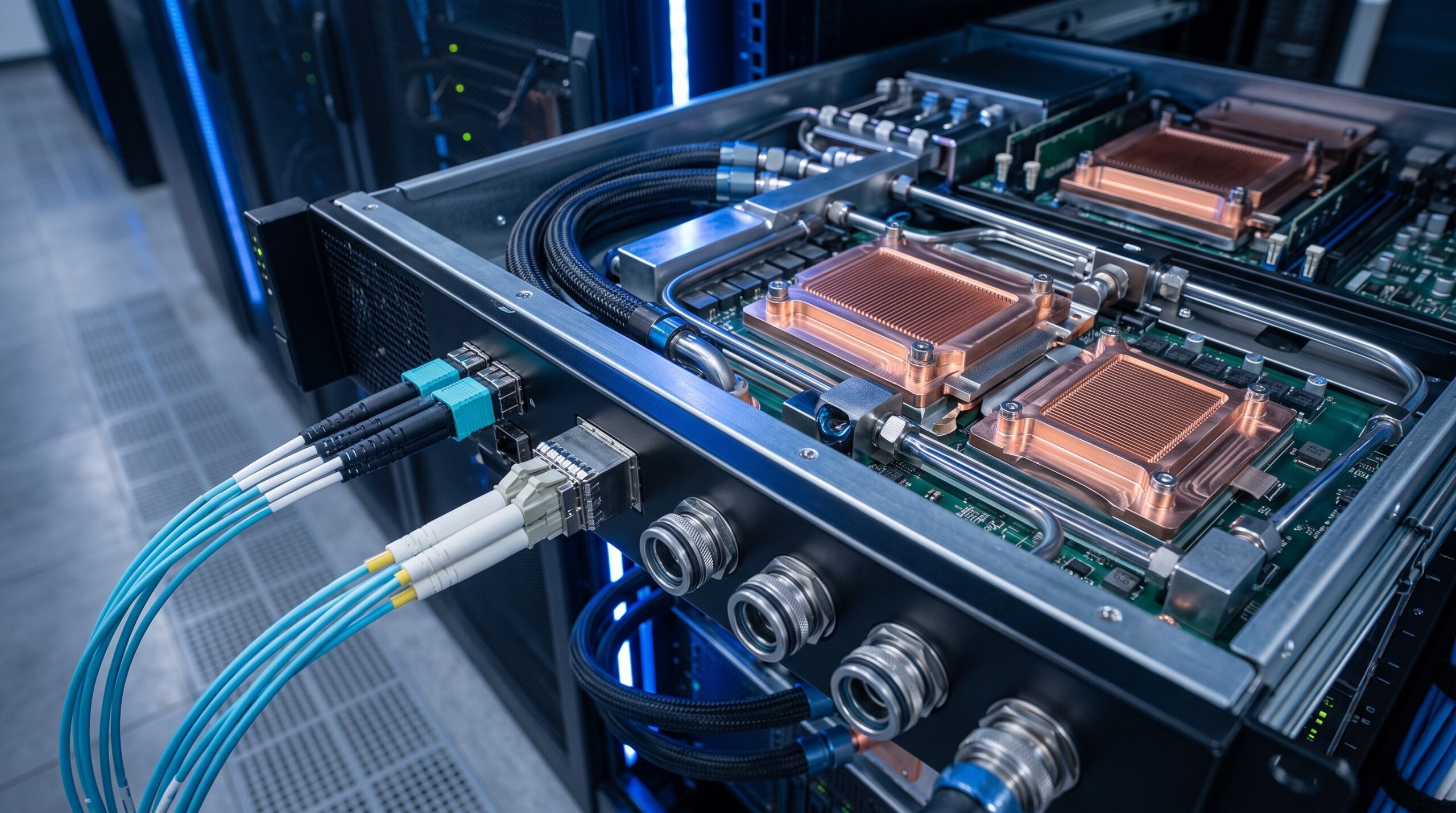
The Cold Plate Liquid Cooling Module System operates as a closed-loop, single-phase or two-phase liquid cooling architecture depending on the selected SKU. The primary thermal transfer path begins at the cold plate, which is mechanically coupled to the high-power ASIC, FPGA, or optical transceiver array via a precision-machined thermal interface. The cold plate extracts heat into the coolant, which is circulated by the CDU pump to the facility water loop through a liquid-to-liquid heat exchanger. The secondary loop manifold distributes coolant to multiple server or line card nodes, ensuring balanced flow rates across all branches.
The control plane is managed by the Thermal Control Firmware Module, which communicates with the chassis management controller via I2C, PMBus, or Ethernet. Real-time telemetry includes inlet and outlet coolant temperatures, flow rate, pressure differential, and leak detection status. The system supports redundant CDU configurations (N+1) and dual-loop isolation for high-availability deployments. All wetted materials are compatible with propylene glycol, ethylene glycol, and dielectric fluorochemical coolants.
DATA & CONTROL PLANE CAPABILITIES
The module exposes a comprehensive sensor and control interface for integration with EMS/NMS platforms. Key data plane parameters include coolant flow rate (L/min), pressure (kPa), temperature (degrees Celsius), and leak detection discrete signals. The control plane supports SNMPv3, Redfish, and Modbus TCP for remote monitoring and threshold-based alarm generation. Firmware upgrades are performed via dual-image flash with rollback capability.
The CDU includes a local touchscreen display for field diagnostics, while the cold plate assembly integrates an optional flow-through temperature sensor with +/-0.5 degrees Celsius accuracy. The leak detection subsystem uses a combination of conductive trace sensors and humidity sensors, with alarm thresholds configurable via the management interface. All alarms are logged with timestamps in non-volatile memory.
COMPONENT BREAKDOWN
1. Cold Plate Assembly: Micro-channel copper or aluminum cold plate with nickel plating, designed for direct-to-chip mounting. Thermal resistance: 0.02 to 0.05 degrees Celsius per Watt. Mounting force: 30 to 70 psi. Compatible with ASIC package sizes from 30 mm x 30 mm to 100 mm x 100 mm.
2. Coolant Distribution Unit (CDU): Rack-mountable 2RU or 4RU chassis containing pump, heat exchanger, reservoir, and control electronics. Pump type: variable-speed centrifugal, MTBF greater than 50,000 hours. Heat exchanger capacity: 10 kW to 80 kW. Redundant pump option available.
3. Secondary Loop Manifold Network: Stainless steel or EPDM manifold with balanced flow design. Ports: 1/4 inch to 1/2 inch quick-disconnect. Flow balancing valves per branch. Maximum operating pressure: 6 bar.
4. Quick-Disconnect Coupling Interface: Dry-break couplings with less than 0.1 mL spillage per disconnect. Materials: chrome-plated brass or stainless steel. Seal material: EPDM or Viton. Rated for 10,000 mating cycles.
5. Leak Detection and Monitoring Subsystem: Conductive trace tape and point sensors. Response time: less than 5 seconds. Alarm output: dry contact and digital bus. Integrated with CDU shutdown logic.
6. Thermal Control Firmware Module: ARM Cortex-M7 microcontroller. Interfaces: I2C, PMBus, Ethernet, USB. Firmware qualified per IEC 61508 SIL-2. Supports redundant firmware images.
OPERATIONAL SPECS MATRIX
The following table summarizes the primary operational parameters for the Cold Plate Liquid Cooling Module System. These specifications apply to standard production SKUs and are subject to change based on configuration.
TECHNICAL SPECIFICATIONS
| Parameter | Specification |
|---|---|
| Form Factor | 2RU CDU / 1RU Cold Plate Manifold |
| Cooling Capacity | 10 kW to 80 kW per CDU |
| Coolant Type | Propylene Glycol 25% / Dielectric Fluorochemical |
| Operating Pressure | 6 bar maximum |
| Flow Rate | 5 to 40 L/min per CDU |
| Temperature Range | 5 to 40 degrees Celsius ambient |
| Power Supply | 1+1 Redundant AC/DC, -48 VDC or 220 VAC |
| Leak Detection Response | Less than 5 seconds |
| Coupling Life | 10,000 mating cycles |
| Compliance | NEBS GR-63-CORE, GR-1089-CORE, UL 62368-1 |
REGULATORY COMPLIANCE
The Cold Plate Liquid Cooling Module System complies with the following standards: IEC 60950-1, IEC 62368-1, NEBS GR-63-CORE, NEBS GR-1089-CORE, RoHS 2011/65/EU, REACH, and WEEE. The CDU is certified to UL 62368-1 and CSA C22.2 No. 62368-1. Leak detection subsystem is qualified to IP54 when installed in a closed rack. Coolant materials are classified as non-hazardous per OSHA 29 CFR 1910.1200. The system is designed for operation in environments with ambient temperatures from 5 to 40 degrees Celsius and relative humidity from 5 to 85 percent non-condensing.
📥 Download Technical Specification
Click the button below to view or download the full official PDF datasheet.

Leave a comment