

SYSTEM OVERVIEW
The High-TDP Network ASIC Micro-Channel Cold Plate Flow Rate Charts document provides a comprehensive engineering analysis of the thermal management subsystem designed for next-generation high-TDP network ASICs. As switching capacities exceed 51.2 Tbps and ASIC thermal design power (TDP) surpasses 1000W, conventional air cooling becomes thermodynamically infeasible. This specification details the micro-channel cold plate architecture, its hydraulic performance envelope, and the corresponding flow rate charts that define safe operating regions for carrier-grade deployments. The document is intended for systems engineers, data center architects, and thermal integration specialists requiring precise guidance on liquid cooling loop design, pressure drop budgeting, and reliability assurance.

INTERNAL ASIC & BACKPLANE
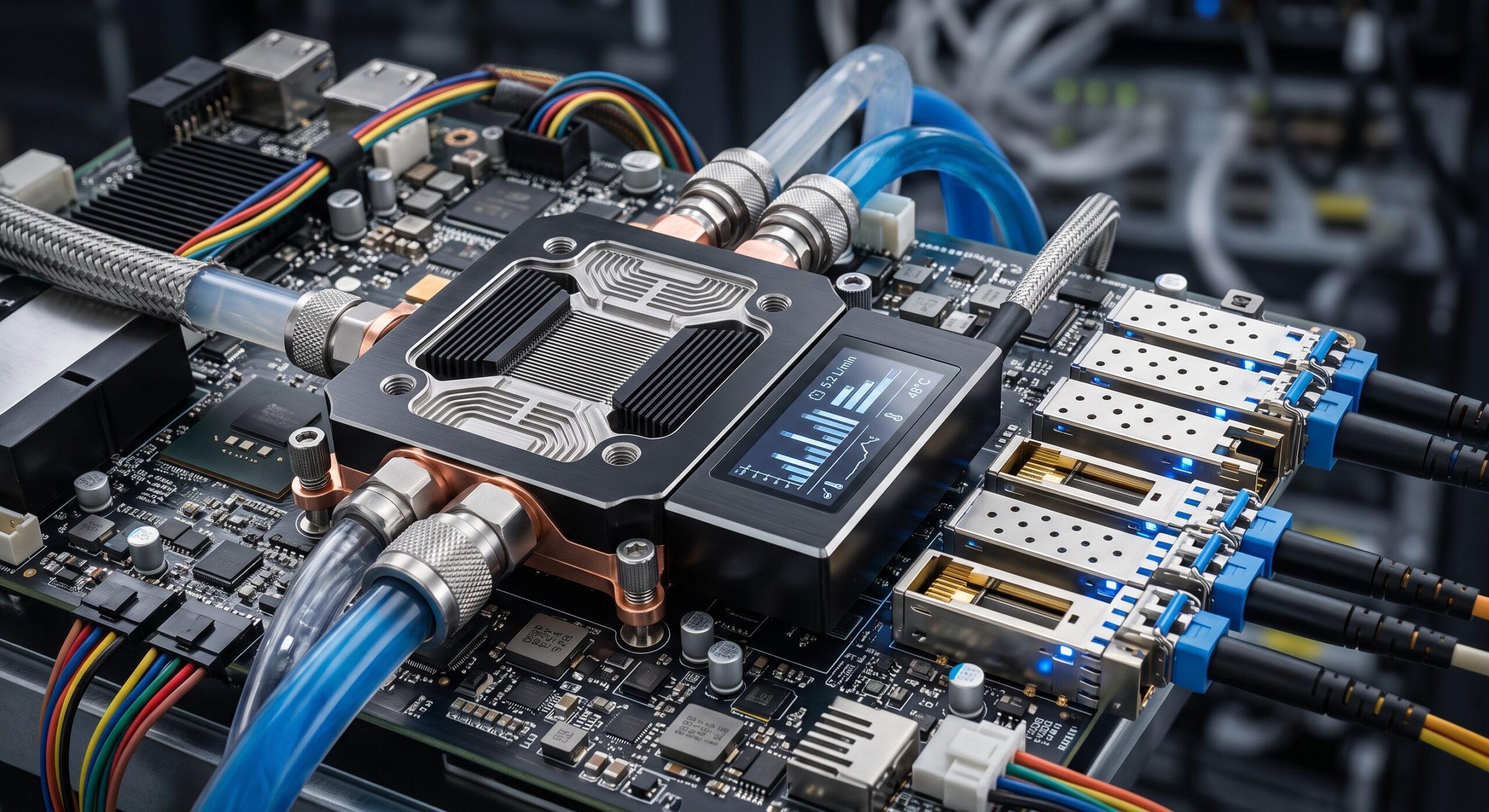
The cold plate is a direct-to-chip, copper-based micro-channel heat exchanger with a brazed stainless steel manifold. It is engineered to interface with a high-TDP network ASIC package (e.g., 100mm x 100mm substrate) via a precision-machined pedestal and a compliant thermal interface material (TIM) with a conductivity of 8.5 W/m·K. The internal micro-channel array features 120 parallel channels, each 0.3 mm wide and 1.5 mm deep, etched into a copper base with a surface roughness (Ra) of less than 0.4 µm. The backplane-side interface includes a leak-proof, blind-mate quick disconnect (QD) coupling rated for 10,000 mating cycles and a maximum operating pressure of 6 bar. The cold plate is designed to maintain a junction-to-inlet thermal resistance (Rth) of 0.015 °C/W at a flow rate of 2.0 L/min using a 50% ethylene glycol-water mixture at 45°C inlet.
POWER & THERMAL MECHANISMS
The thermal mechanism relies on forced convection through the micro-channel array. The flow rate charts presented in this document are derived from empirical testing per ASHRAE 51-2022 and are validated using computational fluid dynamics (CFD) with a k-ω SST turbulence model. The primary hydraulic parameters are flow rate (Q), pressure drop (ΔP), and thermal resistance (Rth). The charts define the operating envelope for three coolant temperatures (40°C, 45°C, 50°C) and two coolant types (deionized water and 25% propylene glycol). Key performance limits include: a maximum pressure drop of 1.2 bar at 3.0 L/min to ensure compatibility with facility-side pumps; a minimum flow rate of 0.8 L/min to prevent flow maldistribution and local boiling; and a burst pressure of 15 bar. The cold plate is qualified for a 10-year life with less than 5% degradation in Rth.
PHYSICAL LIMITS
The cold plate assembly weighs 480 g (dry) and 620 g (wet). It occupies a footprint of 120 mm x 120 mm x 18 mm (excluding fittings). The inlet and outlet ports are 3/8-inch Swagelok® compatible. The unit is RoHS compliant and uses a hermetic seal with a helium leak rate of less than 1×10^-6 mbar·L/s. Operating temperature range is -40°C to +85°C (storage) and +15°C to +65°C (operational). The cold plate is designed to withstand 50 g shock (11 ms half-sine) and 5 Grms random vibration (10-500 Hz).
PARAMETER REGISTRY
The following table summarizes the critical technical specifications. The flow rate charts (provided as separate PDFs in the full datasheet) plot pressure drop versus flow rate for each coolant condition and provide the corresponding thermal resistance curves. These charts are the authoritative reference for loop balancing and pump selection.
| Parameter | Specification |
|---|---|
| Form Factor | Direct-to-chip cold plate, 120 mm x 120 mm x 18 mm |
| Switching Capacity | Supports ASIC TDP up to 1500 W |
| Power Supply | Not applicable (passive hydraulic component) |
| Thermal Resistance (Rth) | 0.015 °C/W at 2.0 L/min, 50% EGW, 45°C inlet |
| Flow Rate Range | 0.8 L/min (min) to 3.0 L/min (max) |
| Pressure Drop | 0.4 bar at 1.0 L/min; 1.2 bar at 3.0 L/min |
| Coolant Compatibility | Deionized water, 25% propylene glycol, 50% ethylene glycol |
| Maximum Operating Pressure | 6 bar |
| Burst Pressure | 15 bar |
| Material | Copper base, stainless steel manifold, EPDM seals |
| Weight | 480 g (dry), 620 g (wet) |
| Operating Temperature | +15°C to +65°C (coolant inlet) |
| Compliance | RoHS, ASHRAE 51-2022, helium leak rate |
GLOBAL SUPPORT INFRASTRUCTURE
Technical support is available 24/7 through the vendor’s global service centers. A dedicated thermal engineering team provides application-specific flow rate chart interpretation, loop design validation, and on-site commissioning support. All cold plates are shipped with a calibration certificate and a QR code linking to the latest digital flow rate charts. A five-year warranty covers defects in materials and workmanship, with an optional ten-year extended warranty including annual performance verification.
📥 Download Technical Specification
Click the button below to view or download the full official PDF datasheet.

Leave a comment