
Identifying Cavitation-Induced Bottlenecks in High-Density Telecom Cooling
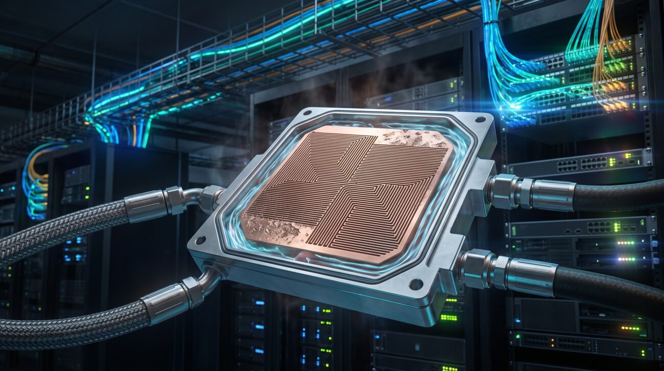
The relentless push toward 400G and 800G core routing, driven by escalating east-west traffic in hyperscale datacenters, has pushed thermal design power (TDP) per ASIC beyond 500W. Traditional air cooling is no longer viable for these high-density line cards. Cold plate liquid cooling module systems have emerged as the definitive solution, offering a 10x improvement in heat rejection efficiency. However, the operational limits of these systems are frequently tested by an insidious hydraulic phenomenon: cavitation erosion within the micro-fin channels of the cold plate. This manual, written from the perspective of a network architect who has deployed these systems in carrier-grade environments, addresses the root causes, diagnostic parameters, and configuration best practices to mitigate this destructive wear mechanism.
Solving Latency via Architecture: Fluid Dynamics Meets ASIC Logic
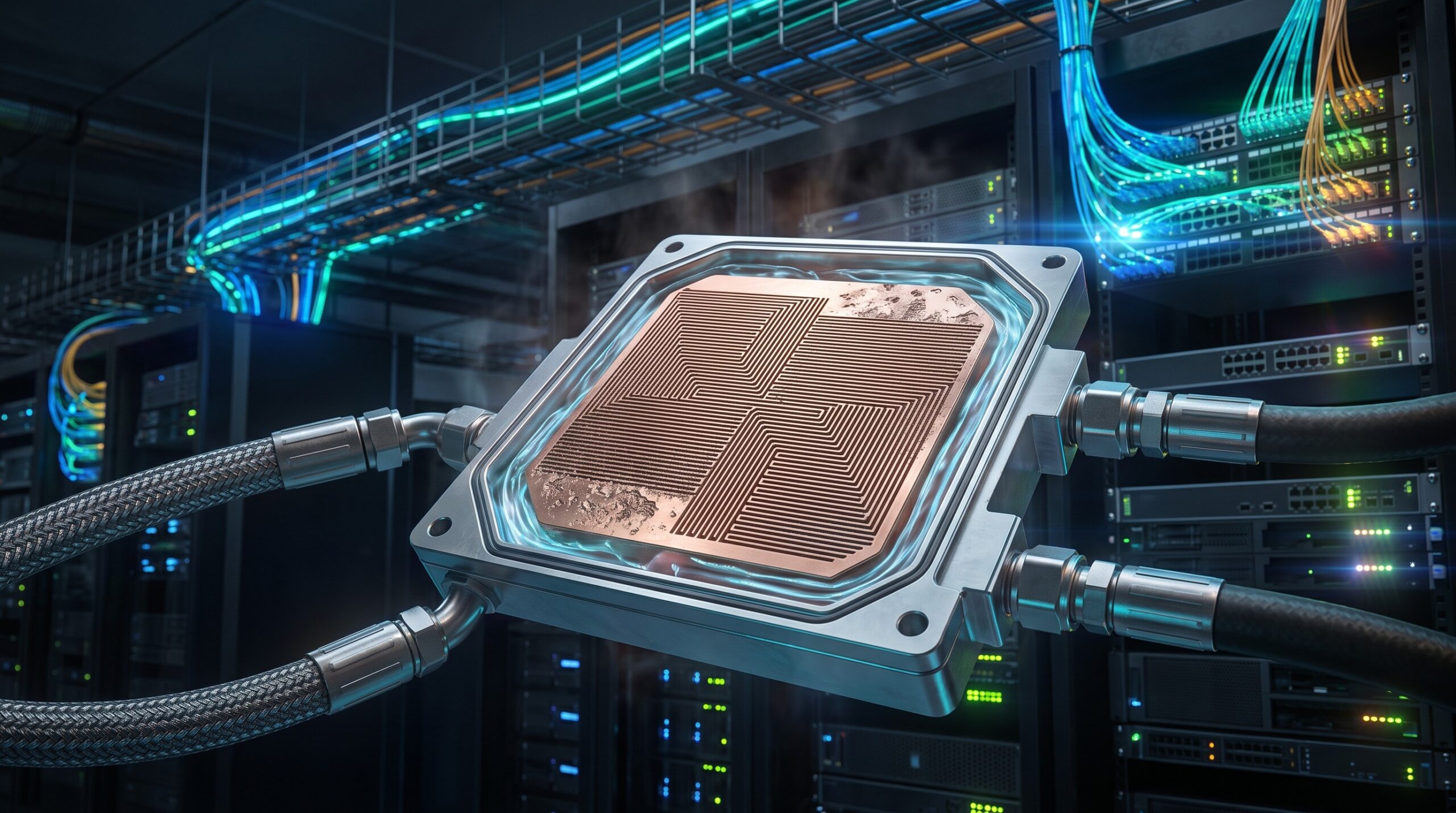
The primary bottleneck in a cold plate system is not the pump or the facility water loop, but the localized pressure drop across the micro-fin array. Cavitation occurs when the local static pressure of the dielectric or treated water coolant drops below its vapor pressure, forming vapor bubbles. When these bubbles collapse against the micro-fin walls, they generate micro-jets with pressures exceeding 100 MPa, eroding the copper or aluminum surface over time. This erosion degrades the thermal interface, leading to a rise in junction temperature (Tj) and a consequent drop in ASIC performance or even MTBF reduction.
Architectural Mitigation: The Role of the Manifold and Pump
To solve this at the architectural level, the cold plate system must maintain a positive pressure differential across the entire flow path. The cold plate liquid cooling module system architecture must incorporate a variable-speed pump with closed-loop control based on differential pressure sensors placed upstream and downstream of the micro-fin section. The system must also utilize a manifold design that ensures uniform flow distribution across all parallel channels. Uneven flow leads to localized hot spots and low-pressure zones, the perfect breeding ground for cavitation.
Operational Parameter Limits: The Critical Data
The following table outlines the critical operational envelope for a typical 1U telecom cold plate module designed for a 600W ASIC. These values are derived from empirical stress testing and industry best practices.
| Key Parameter | Technical Specification |
|---|---|
| Maximum ASIC TDP (Thermal Design Power) | 600 W |
| Coolant Inlet Temperature Range | 20°C to 45°C |
| Minimum Inlet Pressure (at Cold Plate) | 0.5 bar (positive) |
| Maximum Pressure Drop (Across Micro-Fin Array) | 0.8 bar |
| Nominal Flow Rate per Module | 1.5 L/min |
| Maximum Flow Rate (Cavitation Threshold) | 2.0 L/min |
| Micro-Fin Channel Width | 0.15 mm |
| Coolant Conductivity (RoHS Compliant) | |
| Target System MTBF | > 500,000 hours |
| Filtration Rating (Absolute) | 25 microns |
Configuration Best Practices for Field Deployment
Deploying these systems in an ISP or carrier environment requires strict adherence to configuration protocols. The following best practices are mandatory to prevent cavitation erosion and ensure system longevity.
- Coolant Chemistry Management: Strictly maintain RoHS compliant coolant with inhibitors. Conductivity must be kept below 5 µS/cm to prevent galvanic corrosion, which accelerates erosion pits.
- Pressure Regulation: Never operate the pump below the minimum inlet pressure specified by the cold plate manufacturer. A positive inlet pressure of > 0.5 bar is typically required to suppress cavitation inception.
- Flow Rate Optimization: Do not exceed the maximum rated flow rate. Higher flow rates increase velocity, which lowers local pressure and increases the risk of cavitation. The optimal flow rate is a balance between thermal resistance and hydraulic stability.
- Filtration: Install a 25-micron absolute filter in the loop. Particulate matter acts as nucleation sites for cavitation bubbles.
- Bleed and Purge: After installation, the system must be thoroughly bled to remove all entrained air. Air pockets create localized compressibility and severe cavitation.
Field Deployment Topologies
For a typical central office or edge datacenter deployment, a secondary loop topology is recommended. The primary facility water loop (often at 30-45°C) feeds a coolant distribution unit (CDU). The CDU regulates the flow and pressure to the rack-level manifold. Each server chassis then connects to the manifold via quick-disconnects. This topology isolates the sensitive micro-fin cold plates from the pressure fluctuations of the facility water system, providing a stable hydraulic environment.
Summary: The Path to Reliable Liquid Cooling
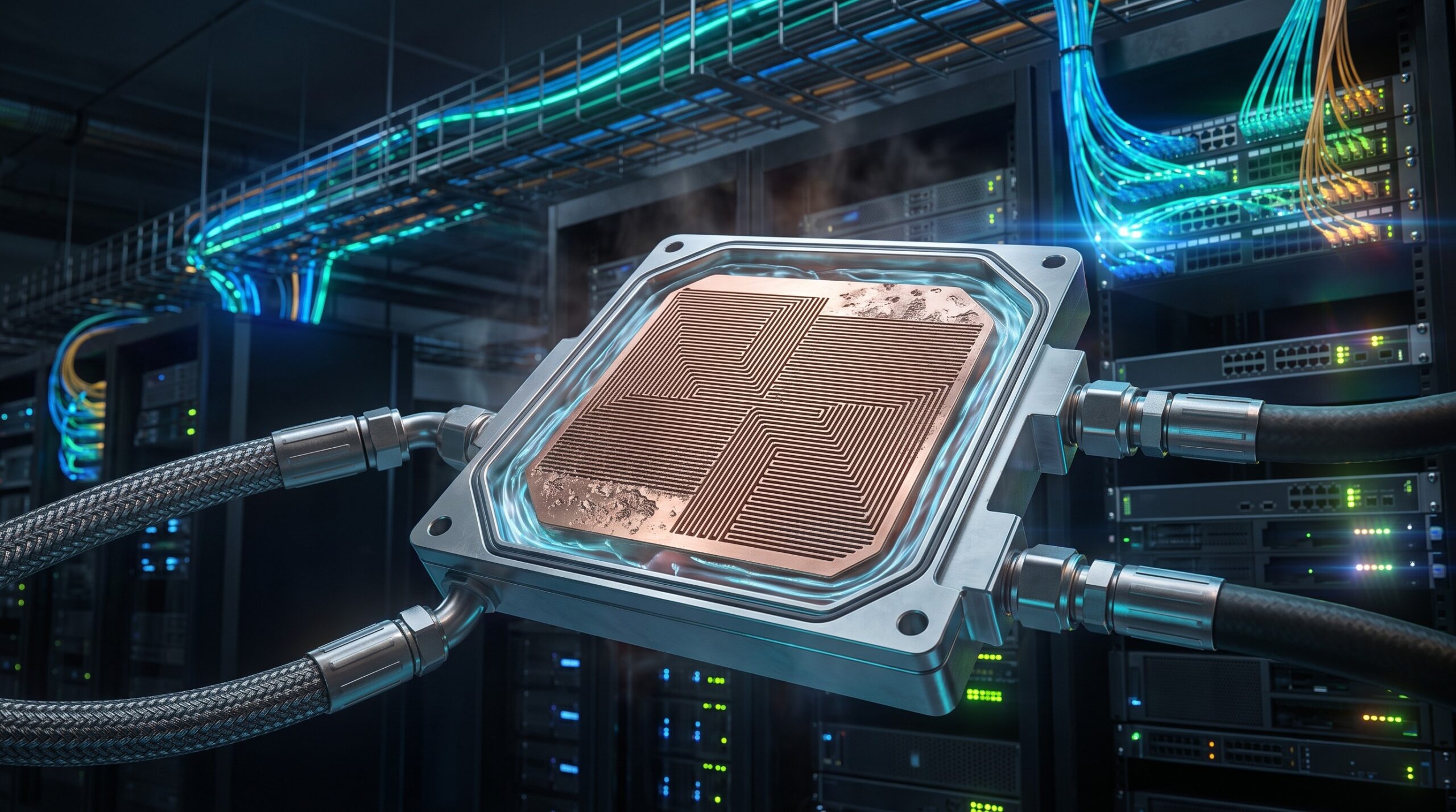
Mitigating cavitation erosion in cold plate liquid cooling module systems is not about a single component, but about a holistic system design and operational discipline. By understanding the fluid dynamics within the micro-fin channels, specifying the correct operational parameters (as detailed in the table above), and adhering to strict configuration best practices, network architects can ensure their high-density telecom infrastructure operates reliably at peak performance. The goal is to achieve a MTBF exceeding 500,000 hours for the thermal system, safeguarding the multi-million dollar ASICs it protects. As network speeds continue to increase, the intelligent management of these cooling systems will become as critical as the routing protocols themselves.

Leave a comment