
Rack Space & Thermal Challenges: The Hydraulic Bottleneck Nobody Budgeted For
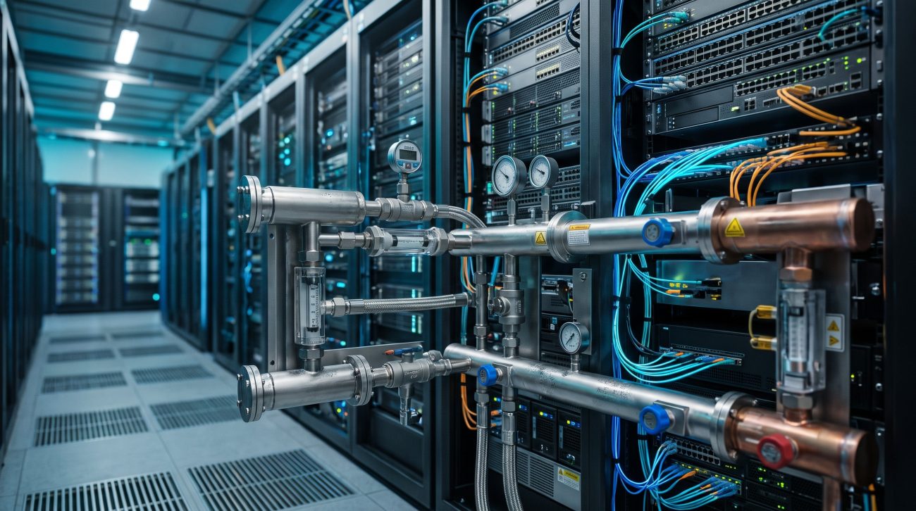
Megawatt-class liquid cooling manifolds are no longer plumbing accessories. They are flow distribution infrastructure that determines whether a 132 kW rack receives its design coolant volume or starves a cold plate into thermal throttling. As rack densities cross the 100 kW threshold and move toward NVIDIA Rubin-era configurations, the hydraulic balancing problem shifts from a mechanical afterthought to a first-order reliability constraint .
The engineering reality is unforgiving: flow maldistribution inside a rack manifold can produce localized overheating on one server while overcooling its neighbor in the same chassis, even when total loop flow satisfies the CDU setpoint. According to IEEE conference research on rack-level two-phase cooling, flow maldistribution among parallel cooling channels under dynamic and nonuniform heat loads remains one of the primary challenges for high-density AI workloads .
Chassis Design & Thermal Dissipation: Flow Distribution as a Switching Fabric
Manifold Topology and the Parallel Branch Problem
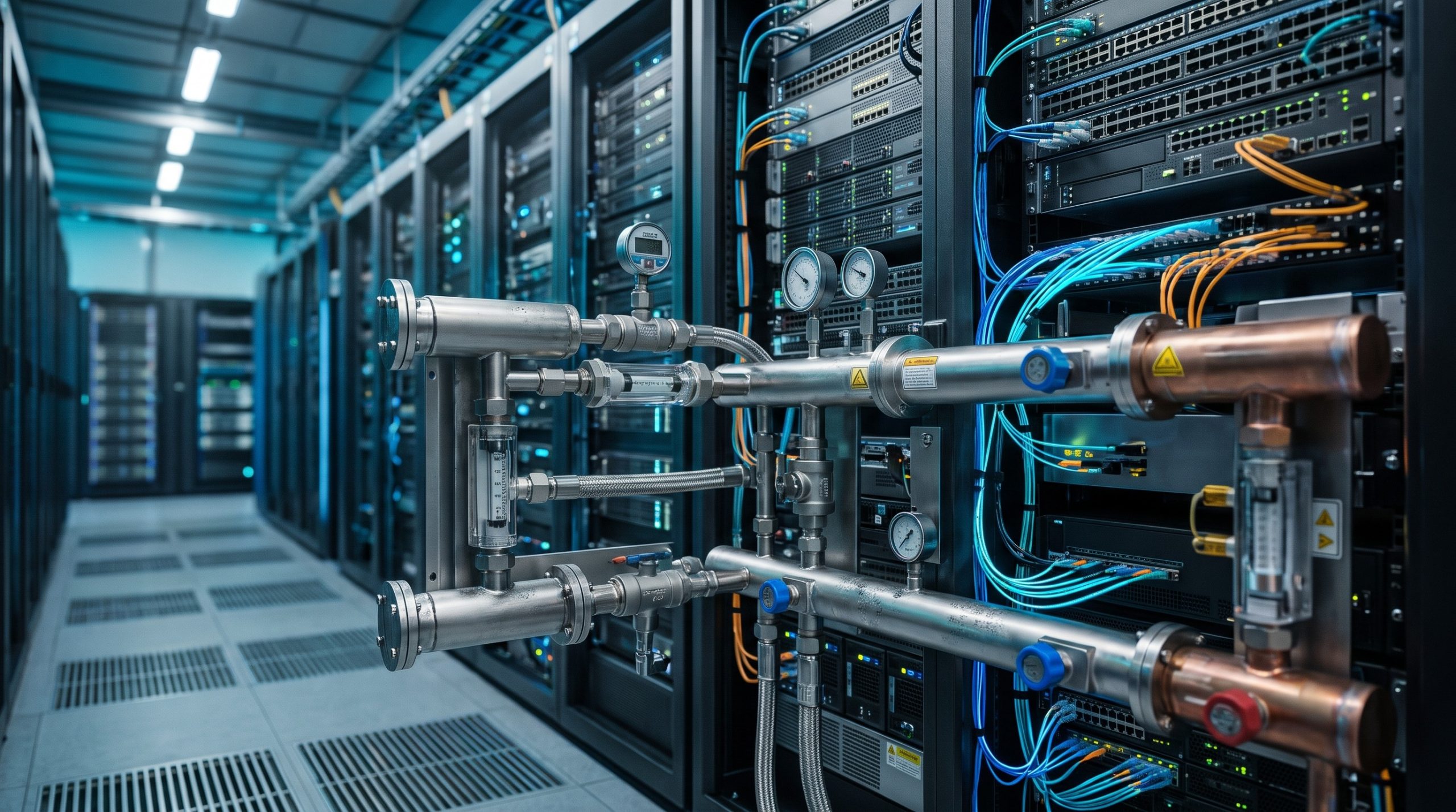
A rack-level manifold is functionally a layer-1 flow switch. It takes a single supply stream from the CDU and fans it out to dozens of parallel server branches, then recollects the return. The hydraulic equivalent of head-of-line blocking occurs when the geometry of the header, the spacing of branch ports, and the internal surface finish create unequal pressure drops across branches. ASHRAE and emerging regional standards now codify what field engineers have measured: branch flow deviation must stay within ±5% under rated conditions for rack-level manifolds, with overall hydraulic balance degree not falling below 90% .
Chinese component manufacturers have also validated this threshold. JONHON specifies that its blind-mate manifold controls flow deviation among heat dissipation nodes within 10%, acknowledging that tighter tolerances require more sophisticated internal flow guidance .
Pressure Drop Economics and Pump Power Penalty
Every unnecessary millibar of pressure drop in the manifold is energy the pump must supply continuously. Polymer manifold configurations using optimized hydraulic geometry have demonstrated approximately 19% lower system pressure loss compared with steel baselines in a 2.1 MW cluster design, with the advantage originating from internal flow guidance and local pressure recovery rather than material selection alone. For a megawatt row running 8,000 hours annually, that delta translates directly into pump power and CDU capacity headroom .
Negative-Pressure Architectures and Transient Stability
Conventional positive-pressure loops carry an inherent leak risk: a failed fitting sprays coolant onto energized busbars. Negative-pressure architectures invert the failure mode—air enters the loop instead of fluid exiting—but introduce pressure fluctuations during vacuum regulation that propagate through the manifold as unsteady flow. Hydraulic balancing in these systems must account for dynamic pressure transients, not just steady-state branch resistance .
Interface Deep Dive: Balancing Metrics That Matter
The following parameters define the operational envelope for a megawatt-class manifold balancing specification. Values reflect commercial-scale direct liquid cooling (DLC) deployments and emerging standardization guidance from ASHRAE and OCP alignment activities .
| Key Parameter | Technical Specification |
|---|---|
| Branch Flow Uniformity (Rack Manifold) | ±5% deviation from mean under rated conditions |
| Hydraulic Balance Degree | ≥ 90% (actual vs. design flow) |
| Flow Adjustment Range | 10%–100% rated flow with ≤±5% linearity error |
| Manifold Local Resistance Coefficient (Supply) | ≤ 2.0 (inlet to branch outlet) |
| Manifold Local Resistance Coefficient (Return) | ≤ 1.5 (branch inlet to outlet) |
| Main Header Friction Loss | ≤ 500 Pa/m at rated velocity |
| Typical Cluster Flow (2.1 MW, 16×132 kW racks) | ~23 L/s at 10°C ΔT with PG25 |
| System Pressure Loss Delta (Polymer vs. Steel) | ~19% lower with optimized polymer geometry |
High-Density Topologies: Active Balancing in Production
Two-Tier Response for Greenfield Megawatt Rows
In a new 2.1 MW cluster served by two liquid-to-liquid CDUs (eight 132 kW racks per CDU), the manifold design must accommodate approximately 23 L/s total volumetric flow at a 10°C ΔT with PG25 coolant. Static balancing valves alone cannot maintain branch uniformity as IT load fluctuates between idle and training bursts. The deployment pattern that works combines passive orifice balancing at the manifold branch level with active control valves at the CDU or row level, providing a two-tier response: fast local equalization and slower global optimization .
For dynamic workloads, pressure-independent control valves (PICV) integrated into rack-level hydraulic modules have demonstrated the ability to absorb excess differential pressure when neighboring branches change load, preventing flow excursions that would otherwise starve adjacent cold plates .
Brownfield Retrofits and the Sidecar Bridge
Operators adding liquid-cooled racks inside air-cooled halls face a different constraint: the existing facility water loop may lack the differential pressure head required for high-flow manifold operation. In these scenarios, a sidecar CDU or pressure-boosting skid becomes necessary, and the manifold must be specified with a wider flow adjustment range (10%–100%) to accommodate variable CDU output during phased IT population .
Fluid Quality as a Balancing Prerequisite
Hydraulic balancing is meaningless if the fluid path is compromised. Cold plate microchannels narrow to a few hundred microns, and debris that a facility loop shrugs off will lodge in a cold plate and degrade thermal performance long before causing outright failure. Ecolab testing across operating data center sites found that roughly 32% of glycol samples fell outside OCP and ASHRAE specification ranges—an indication that fluid-quality validation must precede balancing acceptance .
Commissioning protocols should specify staged flushing (coarse to fine filtration), flow velocities of 0.9–1.5 m/s to keep sediment suspended, and baseline instrumentation capture before the system ever runs a real workload .

Checklist: Manifold Balancing Validation Gates
- Hydraulic balance degree ≥ 90% verified at 50%, 75%, and 100% design flow with all branches populated.
- Branch flow uniformity within ±5% of mean under rated conditions, measured with calibrated inline flow meters.
- Manifold local resistance coefficients confirmed ≤ 2.0 (supply) and ≤ 1.5 (return) via pressure drop sweep.
- Fluid cleanliness meeting OCP/ASHRAE particulate thresholds before balancing valve adjustment.
- Transient response test: simulate hot-swap of one tray and verify neighboring branch flow deviation remains within ±8% during recovery.
- Documentation of baseline differential pressure setpoints for CDU and row-level control valves.
Conclusion: Hydraulic Discipline as Network Architecture
The megawatt data center liquid cooling manifold module is not a passive component in the reliability chain. A manifold that balances well at 50% load but drifts at 100% load forces operators to oversize pumps or accept thermal headroom erosion—both unacceptable at megawatt scale . As OCP and ASHRAE continue to harmonize liquid cooling standards for AI infrastructure, the engineering teams that treat hydraulic balancing with the same rigor applied to packet forwarding and ASIC pipeline design will be the ones who unlock sustained high-density operation without thermal throttling .
Leave a comment