Overview
- Product Profile: A high-density switch engineered for 25GE access combined with 100GE/40GE aggregation. It is commonly deployed as a campus core or building distribution switch, or as a data center leaf (ToR) switch.
- Relevance for 2026: Its port configuration (48×1/10/25G SFP28 + 8×40/100G QSFP28) supports phased network upgrades. You can maintain existing 10G connections, migrate to 25G where needed, and scale uplinks to 100G—all without replacing the chassis.
- Operational Focus: The S6550X-HI series emphasizes enhanced visibility and automation, capable of exporting RDMA-related statistics and alarms via ERSPAN and gRPC, and supports Telemetry.
- Ordering Note: This is a modular platform. Field-replaceable power supplies and fan trays must be ordered separately and planned for correctly, including the required airflow direction.

H3C S6550X-56HF-HI: Engineered for 2026 Networks
Primary Design Purpose
The H3C S6550X-HI series is designed for data center and cloud network environments. It provides high-density ports, modular power and cooling, and 100G ports that are autosensing for 40G/100G and support port breakout functionality.
Within this series, the S6550X-56HF-HI model specifically addresses the “sweet spot” for many enterprise networks evolving toward 2026:
- 25G at the Edge: For server rows, high-performance campus distribution, and other high-bandwidth zones.
- 100G for Uplinks: For building backbones, core interconnects, or leaf-to-spine links.
This combination makes it a practical “bridge” switch for modernizing from 10G/40G infrastructures to 25G/100G without a complete topology redesign.
Verified Model Specifications
Technical Specifications (H3C S6550X-56HF-HI)
| Item | Specification |
|---|---|
| Model | H3C S6550X-56HF-HI |
| Downlink Ports | 48 × 1G/10G/25G SFP28 |
| Uplink Ports | 8 × 40G/100G QSFP28 |
| Switching Capacity | 4.0 Tbps |
| Packet Forwarding Rate | 2800 Mpps |
| Buffer | 24 MB |
| CPU / Memory | 4 cores @ 2.0 GHz; Flash/SDRAM 4GB/8GB |
| OOB Management | 1 × 10/100/1000Base-T management port; console + USB |
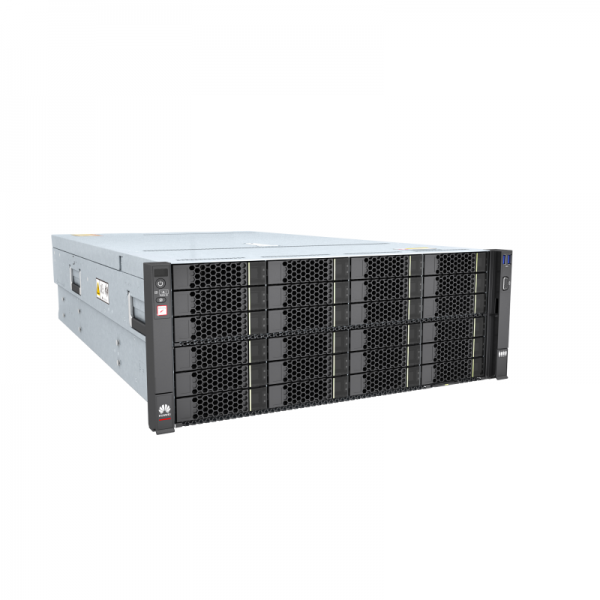
| Form Factor | 1U; 43.6 × 440 × 400 mm; full-loaded weight ≤ 9 kg |
| Power & Cooling | 2 power module slots; 4 fan tray slots; airflow front→rear or rear→front |
| Operating Temperature | -5°C to 45°C |
Series Common Traits:
- Developed for data center/cloud networks; supports modular, hot-swappable PSUs and fan trays with field-changeable airflow direction.
- 100G ports autosense 40G/100G and support breakout configurations.
- Designed with a focus on network “visibility” and automated operations (Telemetry, gRPC/ERSPAN data export).
Core Features & Differentiators
1) High-Density 25G Access: The Practical Upgrade Path
Many networks jump directly from 10G to 100G, incurring unnecessary costs in optics, cabling, and power before workloads require it. 25G often delivers the best return on investment:
- It provides a logical performance step-up from 10G for compute and high-performance edge areas.
- It allows retention of established cabling models while scaling uplink capacity for growth.
- With 48 multi-rate SFP28 ports, this switch supports mixed environments—legacy 10G today, new 25G deployments tomorrow—without a disruptive overhaul.
2) Design Flexibility: 8× QSFP28 Uplinks with Breakout
The uplink capability transforms this switch into a serious aggregation contender:
- 8 × 40/100G QSFP28 ports for core/distribution or leaf-to-spine connectivity.
- QSFP28 ports are 40G/100G autosensing, and each can be split into four interfaces.
Design Implications:
- In a building distribution role, 8 uplinks provide ample ports for dual-homing and future expansion.
- In a leaf (ToR) role, breakout allows conversion of a 100G port into 4×25G lanes, matching expansion patterns for additional racks or dense endpoint zones.
3) Forwarding Headroom for Stable Aggregation
While specifications aren’t everything, they are critical when aggregating numerous links and policies:
- 4.0 Tbps switching capacity and 2800 Mpps forwarding rate provide substantial headroom for dense 25G access and heavy east-west traffic patterns.
4) Resilient Topologies: IRF2 Stacking & M-LAG
The S6550X-HI platform emphasizes two high-availability patterns:
- IRF2: Virtualizes multiple physical switches into a single logical device, aiming for fast convergence (datasheet cites under 50 ms) and unified management.
- M-LAG: Enables device-level link backup and supports independent upgrades of dual-homed devices, minimizing maintenance impact.
Practical Guidance:
- Choose IRF2 for a “single logical box” operational model, ideal for campus core or building distribution.
- Choose M-LAG for a “two physical boxes, one logical uplink domain” approach, offering controlled failure domains for dual-homed servers or aggregation.
5) Data Center Features: Lossless Ethernet & VXLAN
The datasheet highlights “abundant data center features,” including:
- PFC, ECN, and DCBX for lossless, low-latency Ethernet (beneficial for storage/HPC/RDMA traffic).
- VXLAN hardware gateway capability for network virtualization and multi-tenancy.
- Support for DCB, RoCE, and OAM as part of its high-performance services positioning.
Application Advice:
- If not currently using RDMA or lossless fabrics, treat these as future-proofing capabilities.
- If building AI/HPC/storage zones sensitive to packet loss, these features help integrate such workloads into a common Ethernet fabric.
6) Intelligent Operations: ERSPAN, gRPC & Telemetry
H3C positions the S6550X-HI around “data center visualization.” It can export real-time resource data, statistics, and RDMA alarms via ERSPAN and gRPC to an O&M platform for tracing, troubleshooting, and optimization.
- H3C provides a dedicated Telemetry Configuration Guide (including gRPC) for this series, indicating it’s a fully documented operational feature, not just a marketing point.
7) Flexible Cooling & Modular Design
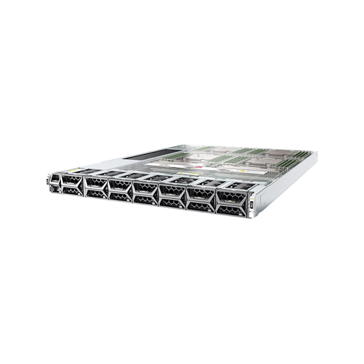
The platform supports modular power supplies and fan trays, with field-changeable airflow direction.
- You must install four identical fan trays.
- Model dictates direction: FAN-40B-1-A (port→power) and FAN-40F-1-A (power→port).
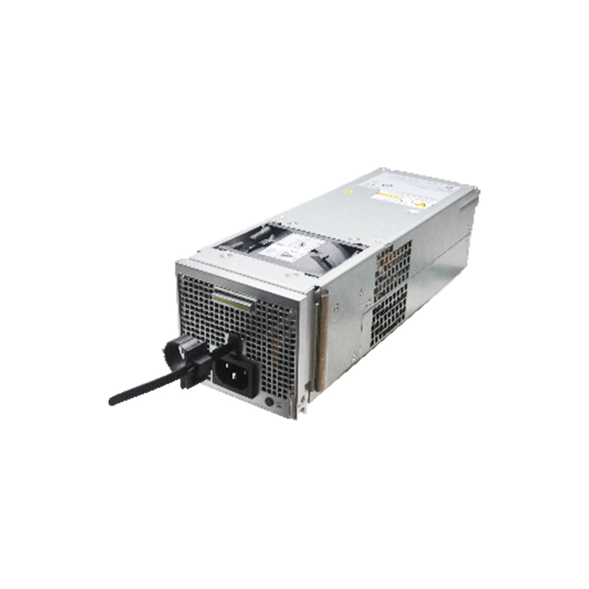
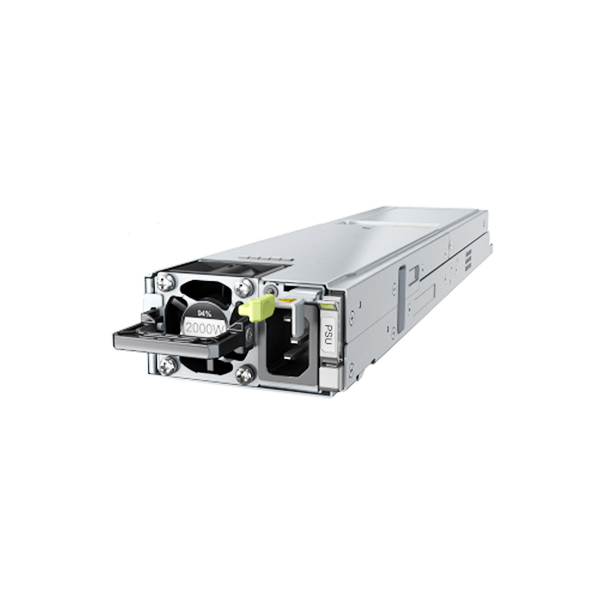
- PSU options (e.g., PSR450-12A, 12D) support 1+1 redundancy.
- Planning this correctly prevents common deployment issues like thermal alarms due to airflow mismatch.
Ideal Deployment Scenarios
Scenario 1 – Campus Core / Building Distribution Upgrade
Ideal for relieving uplink congestion between buildings or distribution layers. It delivers:
- 25G aggregation for high-demand floors or zones.
- 100G backbone connectivity for core links.
Scenario 2 – Data Center Leaf (ToR) for Mixed Server Environments
Naturally fits as a ToR switch in overlay or integrated networks. The port template (48×SFP28 + 8×QSFP28) aligns with common leaf-to-spine designs, especially when standardizing on a single leaf model for various rack types.
Scenario 3 – Edge Room or Mini-DC Aggregation
Suited for edge computing locations (branch, factory, enterprise edge rooms) that require:
- Dense 10G/25G endpoint connectivity.
- Clean 100G uplinks to a central core.
- Manageable O&M visibility for remote sites. Features like Telemetry are particularly relevant here.
Scenario 4 – RDMA or Low-Latency Zones
For workloads sensitive to packet loss or jitter (AI, HPC, storage), the PFC/ECN/DCBX and RoCE support enables the creation of controlled “lossless islands” within a broader Ethernet network.
Scenario 5 – High Fan-in Aggregation
When aggregating traffic from many access switches (multiple IDFs or racks), the 8 uplink ports and robust forwarding headroom help maintain predictable, manageable oversubscription.
Recommended Accessories & FRUs
| Category | Options | Notes |
|---|---|---|
| Power Supplies | PSR450-12A / 12A1 / 12AHD / 12D | 450W class; supports 1+1 redundancy. The ‘D’ model supports -48V DC input. |
| Fan Trays | FAN-40B-1-A (port→power) / FAN-40F-1-A (power→port) | Must install four identical fan trays. |
| Expansion Modules | LSWM2EC / LSWM2-iMC / LSWM2FPGAB / LSPM6FWD | Optional for enhanced management or traffic analysis. |
| Optics & Cabling | 25G SFP28; 100G QSFP28; DAC/AOC | Choose SR/LR based on distance. Standardize to reduce operational costs. |
Quick Comparison Guide
Focus on role fit, not brand preference.
| Feature | H3C S6550X-56HF-HI | H3C S6530X-48Y8C | Cisco Catalyst 9500-24Y4C |
|---|---|---|---|
| Downlinks | 48×1/10/25G | 48×10/25G | 24×25G |
| Uplinks | 8×40/100G | 8×100G | 4×100G |
| Virtualization | IRF2 | IRF2 / M-LAG | StackWise / SVL |
| Best-Fit Role | Campus Core / DC Leaf | L3 Aggregation | Enterprise Aggregation/Core |
FAQs: Practical Guidance
Q1: Is this a campus or data center switch?
A: It is designed for data center and cloud networks but is equally effective as a high-performance campus distribution or core switch. Its role depends on your network architecture.
Q2: What is the exact port configuration?
A: 48×1/10/25G SFP28 downlinks and 8×40/100G QSFP28 uplinks.
Q3: Do the QSFP28 ports support both 40G and 100G?
A: Yes. Series documentation confirms the 100G ports are 100G/40G autosensing.
Q4: Can I use breakout cables on the QSFP28 ports?
A: Yes. H3C states each 100G port can be split (typically 100G→4×25G).
Q5: What are the switching capacity and forwarding rate?
A: The datasheet lists 4.0 Tbps switching capacity and 2800 Mpps packet forwarding rate.
Q6: Does it support IRF2 and what are the benefits?
A: Yes. IRF2 virtualizes multiple devices for simplified management and high availability, with a claimed sub-50ms convergence time.
Q7: When should I choose M-LAG over IRF2?
A: Choose M-LAG when you need device-level redundancy for dual-homed endpoints and the ability to upgrade devices independently without a full outage.
Q8: Do I need lossless Ethernet features (PFC/ECN/DCBX)?
A: Primarily if you are running storage, HPC, or RDMA workloads that require low loss and predictable latency. The switch includes these as part of its data center feature set.
Q9: What O&M capabilities are highlighted?
A: The series emphasizes visibility through exporting real-time stats and alarms (including RDMA data) via ERSPAN and gRPC, and supports Telemetry. A dedicated configuration guide is available.
Q10: What are the compatible PSU and fan models?
A: PSUs: PSR450-12A / 12A1 / 12AHD / 12D. Fan Trays: FAN-40B-1-A (port→power) or FAN-40F-1-A (power→port).
Q11: Can I mix different fan tray models in one chassis?
A: No. The hardware guide requires installing four identical fan trays for proper thermal performance.
Q12: What should I confirm before ordering?
A: Verify your (1) uplink speed and breakout requirements, (2) PSU model and redundancy plan, and (3) required airflow direction (fan tray model). This prevents most deployment issues.
Conclusion
The H3C S6550X-56HF-HI is a compelling, future-ready platform for deploying a dense 25G edge with multiple 100G uplinks, whether as a campus core/distribution switch or a data center leaf.
Its key strengths lie in a practical port template (48×SFP28 + 8×QSFP28), robust performance headroom (4.0 Tbps, 2800 Mpps), a modular design with selectable airflow, and an operational framework built on enhanced visibility via ERSPAN, gRPC, and Telemetry.
For more detailed specifications and documentation, visit telecomate.com.


Leave a comment