 Introduction 7")
With the surge in popularity of AI, more and more customers are focusing on storage devices. This article introduces the Huawei 2 U Controller Enclosure of OceanStor Dorado 5000/6000 (NVMe).
Overview
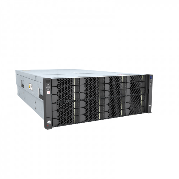
The controller enclosure uses a modular design and consists of a system subrack, controllers (with built-in fans), power-BBU modules, and disk modules. A single controller enclosure supports two controllers.
Overall Structure
It shows the overall structure of a 2 U 36-disk controller enclosure.
Overall structure of a 2 U 36-disk controller enclosure.
 Introduction 8")
NOTE: The controllers are A and B from top to bottom. Controllers communicate with each other using internal heartbeat and mirroring links and do not need cable connections.
Front View
It shows the front view of a 2 U 36-disk controller enclosure.
Front view of a 2 U 36-disk controller enclosure.
 Introduction 9")
NOTE:
- The disk slots of a 2 U 36-disk controller enclosure are numbered 0 to 35 from left to right.
- Slots are used to accommodate and secure disks, interface modules, controllers, and power-BBU modules.
- The information plate is used to record device information. You can pull out the information plate near the mounting ear of the device to view the device model.
It shows the rear view of a controller enclosure.
Rear view of a controller enclosure (using the AC power module as an example).
 Introduction 10")
NOTE:
- Do not connect the management network port and maintenance network port to the same LAN or switch to prevent network loops.
- Only serial cables can be inserted into serial ports. Do not insert network cables into serial ports.
NOTE:
- The controllers are A and B from top to bottom. Each controller has six interface module slots, which are numbered IOM 0, IOM 1, IOM 2, IOM 3, IOM 4, and IOM 5 from left to right and from top to bottom.
- The rules for installing interface modules on a controller enclosure are as follows:
- The scale-out interface module must be installed in slot IOM 2 of each controller.
- A maximum of six 100 Gbit/s RDMA back-end expansion interface modules can be installed in a sequence of IOM 5 > IOM 4 > IOM 3 > IOM 1 > IOM 0 > IOM 2.
- Install front-end interface modules in a sequence of IOM 0 > IOM 3 > IOM 1 > IOM 4 > IOM 5 > IOM 2.
- The installation sequence of interface modules used for replication services is the same as that of front-end interface modules.
- Interface modules of the same type must be installed in sequence.
- Install different types of front-end interface modules in a sequence of Ethernet > RoCE > FC. Place interface modules in ascending order of their port rates.
- Each controller supports a maximum of two SmartDedupe and SmartCompression acceleration modules. Follow this order when installing SmartDedupe and SmartCompression acceleration modules into slots: IOM 5 > IOM 4 > IOM 3 > IOM 1 > IOM 0 > IOM 2.
- The onboard expansion ports are 100 Gbit/s RDMA ports.
- The maintenance network port is used for special management and maintenance only by Huawei technical support engineers in emergency. The initial IP address of the maintenance port is 172.31.128.101 or 172.31.128.102. The default subnet mask is 255.255.0.0. You are advised to connect only the management network port to the network.
If you have any demands or questions for OceanStor Dorado 5000/6000, please feel free to contacat csd@telecomate.com.


Leave a comment