
Overview & Thematic Scope
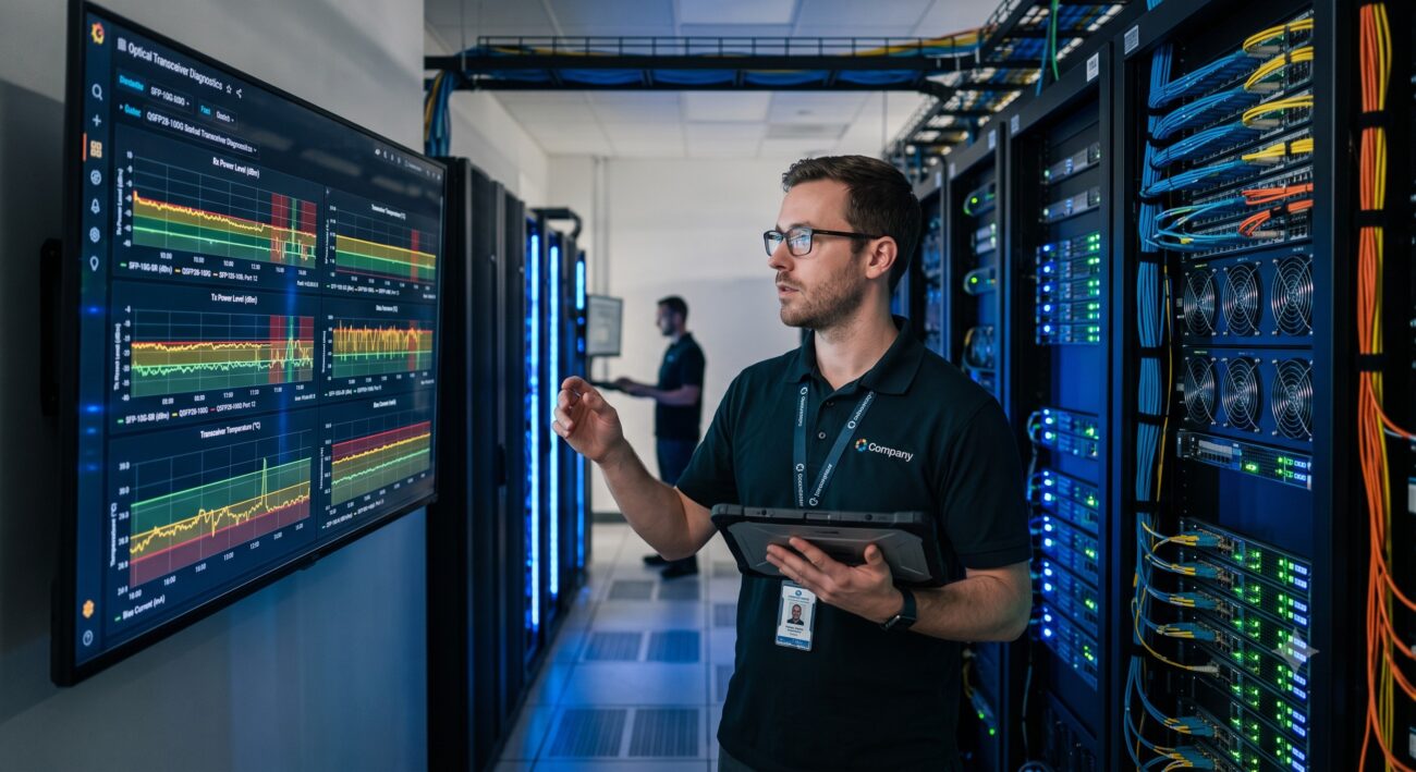
This FAQ addresses the critical role of Digital Optical Monitoring (DOM) and Digital Diagnostics Monitoring Interface (DDMI) in modern SFP transceivers. As a network engineer, understanding these functions is essential for proactive network maintenance and troubleshooting. This guide focuses specifically on optical interface compatibility and the operational intelligence provided by these monitoring features.
Frequently Asked Questions
- Q1: What exactly does the DOM/DDMI function do on an SFP module?
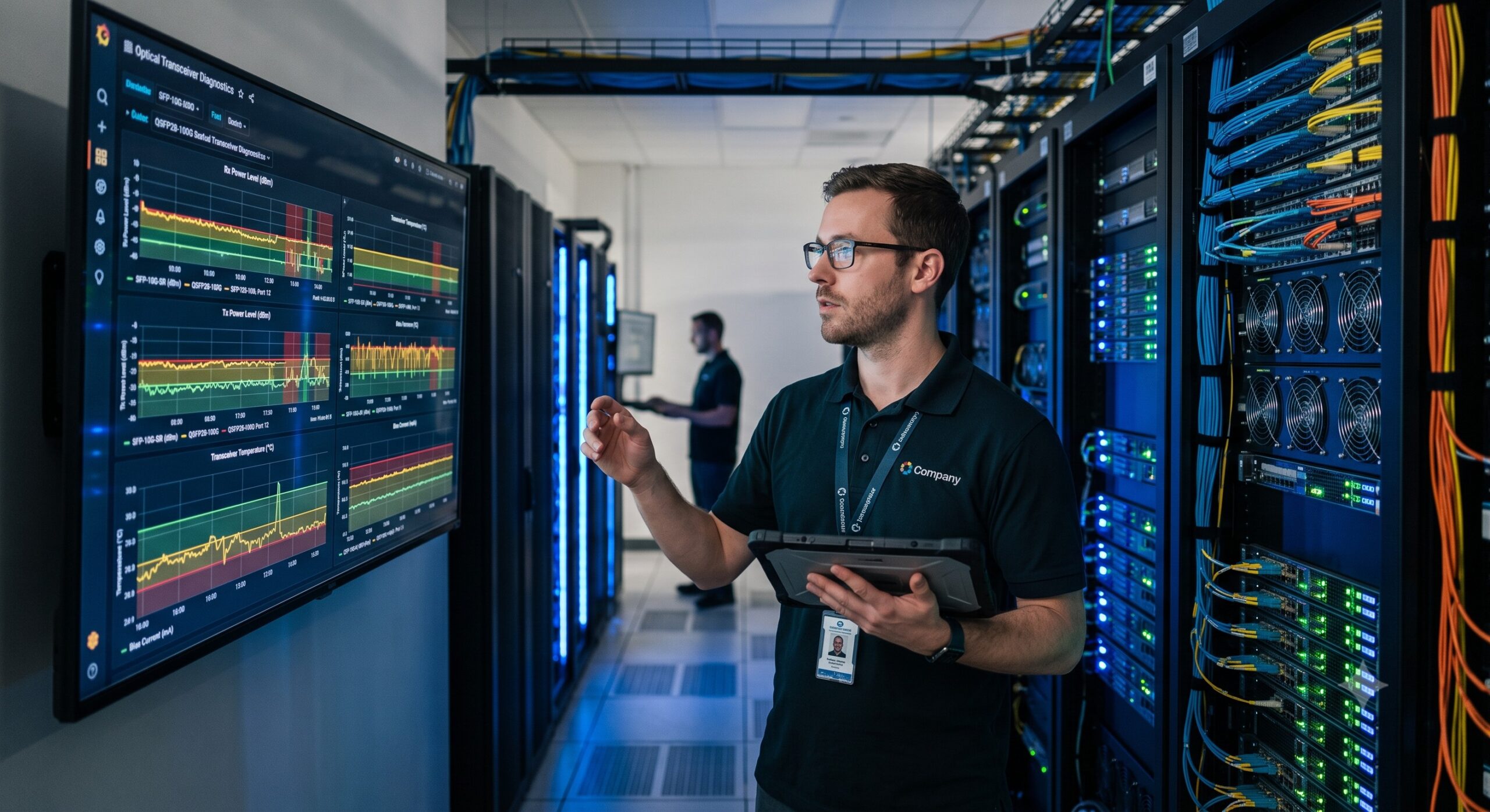
- DOM/DDMI provides real-time, in-service monitoring of key optical parameters directly from the SFP transceiver. It allows the network host device to track metrics like optical output power, received optical power, temperature, voltage, and bias current, enabling proactive fault detection and performance management.
- Q2: Why is DOM/DDMI critical for network troubleshooting?
- DOM/DDMI data is essential for isolating faults in the physical layer by providing clear thresholds for performance degradation. By monitoring parameters like TX Power and RX Power, engineers can quickly pinpoint whether an issue originates from a failing transceiver, a dirty fiber connector, or a problem with the fiber link itself, drastically reducing Mean Time To Repair (MTTR).
- Q3: Is DOM/DDMI functionality compatible with all SFP ports and switches?
- While DOM/DDMI is an industry-standard MSA (Multi-Source Agreement) feature, its full functionality depends on both the SFP module’s firmware and the host switch’s support for reading the diagnostic data via the I2C interface. Most modern enterprise and data center switches support it, but legacy hardware may not display the detailed diagnostic parameters.
- Q4: How can I check if my SFP module supports DOM/DDMI?
- You can verify DOM support by checking the module’s datasheet or using the CLI command on your switch (e.g., `show interface transceiver details`). The output will explicitly list the DOM/DDMI capabilities and display real-time values for temperature, voltage, current, and power levels if the feature is enabled and supported.
- Q5: What are the standard alarm and warning thresholds for DOM/DDMI parameters?
- Alarm and warning thresholds are predefined per SFP type and are stored in the module’s EEPROM. For a standard 10km SFP, typical TX Power is between -3 to -9 dBm. Exceeding these high or low thresholds triggers an alarm, alerting the network administrator to potential hardware failure or link issues before they cause an outage.
- Q6: Can I use DOM/DDMI data to predict SFP transceiver failure?
- Yes, trending DOM/DDMI data allows for predictive maintenance. For example, a gradual increase in TX Bias Current over time indicates that the laser diode is aging and will eventually fail. This data enables proactive replacement during scheduled maintenance windows, preventing unexpected network downtime.
- Q7: What is the difference between DDMI and DOM?
- In the industry, these terms are often used interchangeably, but DDMI refers specifically to the digital interface and protocol for monitoring, while DOM refers to the actual diagnostic monitoring capabilities. Both provide the same critical performance data. The key takeaway is that a DOM-enabled SFP provides the data, and DDMI is the means to access it.
- Q8: What troubleshooting steps should I take if DOM/DDMI is reporting an error?
- First, check the reported metrics: a low RX Power often points to a dirty connector, high attenuation, or a broken fiber. A high TX Power or Bias Current could indicate a failing laser. Cross-reference the data with the optical link budget to determine if the signal is within acceptable limits, and inspect physical connectors before replacing the transceiver.

Leave a comment