
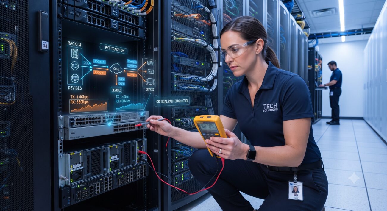
Overview & Thematic Scope
CAN bus communication is the backbone of modern digital rectifier systems, enabling critical functions like current sharing, voltage adjustment, and remote monitoring. When communication between the controller and rectifier modules fails, it can trigger alarms such as ‘Rectifier Lost’ or ‘All Rectifiers Comm Fail,’ leading to system instability or downtime . This FAQ provides systematic troubleshooting guidance for network engineers and telecom technicians, covering the most common hardware and software failure points in CAN bus rectifier networks.

Frequently Asked Questions
- Q1: What are the first physical checks to perform when rectifier modules lose CAN bus communication?
- Begin by verifying all physical connections and wiring integrity. The most common cause of communication loss is a loose or faulty connection .
- Ensure all rectifier modules are securely seated and tightly screwed into the shelf .
- Check that CAN_H and CAN_L cables are securely connected and correctly routed between shelves and to the controller .
- Verify wiring is not reversed; CAN-H typically connects to CAN-H and CAN-L to CAN-L .
- Inspect cables for physical damage, breaks, or loose connections .
- Q2: How do CAN bus termination resistors affect communication with rectifier modules?
- Improper termination is a frequent cause of unstable or failed CAN bus communication in rectifier systems. The CAN bus requires a 120-ohm termination resistor at each end of the bus to prevent signal reflections .
- When multiple rectifiers with internal 120-ohm termination are connected in parallel, the total parallel resistance drops below 60 ohms, making the bus unstable .
- Use a CAN bus analyzer or multimeter to measure resistance between CAN_H and CAN_L; a healthy bus should read approximately 60 ohms .
- Ensure only the two physical ends of the bus have termination enabled.
- Q3: What do ‘Rectifier Communication Lost’ and ‘All Rectifiers Comm Fail’ alarms indicate?
- A ‘Rectifier Lost’ or ‘Communication Fail’ alarm signals that the controller is no longer receiving data from one or more rectifier modules .
- These alarms typically trigger after the controller detects no CAN messages for a defined period, such as ten seconds .
- They can indicate a failed rectifier, a communication cable break, or a faulty controller .
- Check the controller’s alarm log to determine if the failure is isolated to a single module or affects the entire bus .
- Q4: Can firmware or software mismatches cause CAN bus communication errors?
- Yes, firmware and software version mismatches are a known cause of CAN bus communication problems and load-sharing errors. In systems with multiple rectifiers, controllers can generate alarms when rectifiers with different software revisions are detected on the CAN bus .
- This can lead to a ‘Rectifiers Limited’ or ‘Load-share Problem’ alarm .
- Ensure all rectifier modules in a system are running compatible or identical firmware versions.
- When replacing a module, verify its firmware is compatible with the rest of the system to avoid communication errors .
- Q5: How can I diagnose ‘CANopen communication fault’ (E_CAN) or code 14 errors on my rectifier?
- These specific error codes point to serial communication failures on the CAN bus. The cause is often an improper system setup or a hardware failure .
- Code 14 (Rectifier Control CAN Bus Reception Failure): Usually indicates a connection problem between the system and the rectifier control card or a fault with the control card itself .
- E_CAN (CANopen Communication Fault): This generic fault can result from an incorrect baud rate setting, a serial communication error, or a long communication interruption. Check and set a proper baud rate, verify cabling, and perform a system reset .
- Q6: What is the proper procedure to recover a rectifier after a communication failure?
- After the root cause is resolved, a structured recovery and reassignment process is often necessary to restore normal operation .
- Hard Reset: Power off the ESP32/controller and the rectifier, disconnect all CAN connections, and then reconnect them following the precise wiring diagram .
- Software Reassignment: If the controller uses an inventory management system, you may need to manually reassign or ‘assign’ the rectifier module. A device that was ‘Forgotten’ will typically auto-assign once it is rediscovered on the CAN bus .
- If the rectifier remains in a hibernate state, you may need to send a manual CAN ON command or check for missing jumpers .
- Q7: Where do I start if I suspect the controller itself is causing the CAN bus failure?
- If physical cabling and module firmware are confirmed, the controller (e.g., SMU, CXC HP) should be considered as a potential failure point .
- An ‘All Rectifiers Comm Fail’ alarm is a strong indicator of a controller or main bus issue .
- Check the controller’s power and reseat the unit to clear any temporary faults .
- If other rectifiers on the same bus are communicating, the issue is likely with the individual module, not the controller.
- If the controller is faulty, it may need to be replaced .

Leave a comment