
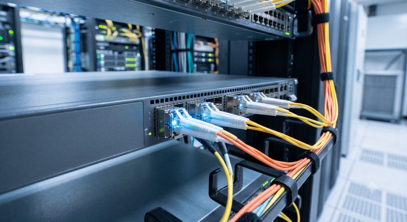
Introduction: The Modular Foundation of Modern Networks
In the architecture of enterprise and carrier-grade networks, the Small Form-factor Pluggable (SFP) port has evolved from a simple interface into a strategic asset for network design. As a Senior Network Architect, I view the SFP ecosystem not merely as a collection of ports, but as a highly flexible physical layer abstraction layer that decouples the switch hardware from the transmission media. This comprehensive guide provides a deep dive into the SFP ports on switches, covering their architectural nuances, performance metrics, and deployment best practices, offering a data-driven evaluation for telecom hardware engineers and systems integrators .
Today, SFP ports are ubiquitous across network equipment, from enterprise aggregation switches to high-density data center spines. Their value lies in modularity—the ability to hot-swap transceivers to support various cabling types, distances, and speeds without replacing the entire switch . This guide dissects the engineering specifications, from the ASIC interfaces to the physical layer compliance, providing a definitive reference for optimizing your network infrastructure.
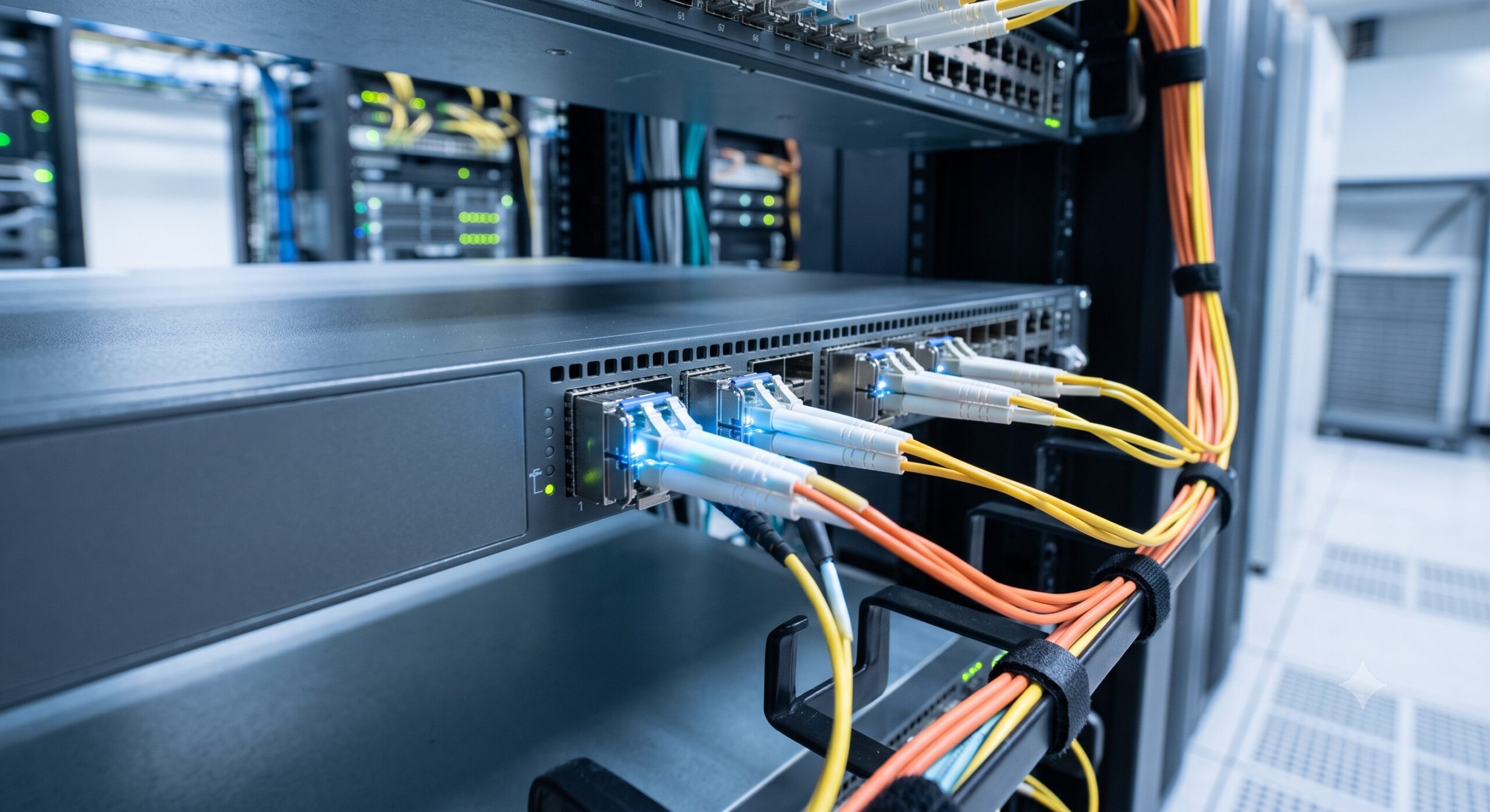
Core Architecture & Hardware Topology of SFP Ports
Understanding the SFP Ecosystem: From Cage to MAC
An SFP port on a switch is more than just a physical slot; it is a standardized interface defined by the Multi-Source Agreement (MSA). The architecture begins with the physical cage on the switch panel, which provides the mechanical and electrical interface. Inside, the switch’s Application-Specific Integrated Circuit (ASIC) or Network Processor houses the SerDes (Serializer/Deserializer) lanes that drive the high-speed electrical signals . The SFP module itself converts these electrical signals to optical (or copper) signals for transmission. This separation is key: the switch’s silicon determines the port’s maximum speed capability (e.g., 1G, 10G, 25G), while the module determines the media type and reach .
Data flow is governed by industry standards. The IEEE 802.3 family defines the Ethernet protocols for each speed grade:
- SFP (1G): Standardized by IEEE 802.3z for 1000BASE-X .
- SFP+ (10G): Standardized by IEEE 802.3ae for 10GBASE-R .
- SFP28 (25G): Standardized by IEEE 802.3by for 25GBASE-R .
When designing a network, the SFP port serves as the primary interface for fiber uplinks, server connections, and inter-switch links (ISLs). The switch hardware description documents, such as those from Huawei, confirm that 10GE SFP+ ports often support auto-sensing to 1000 Mbit/s, allowing backward compatibility with older SFP modules . This architectural choice provides a seamless migration path from 1G to 10G infrastructures.
Combo Ports vs. Uplink Ports
Understanding the different physical port types is crucial for deployment. Two common types are Combo Ports and Uplink Ports:
- SFP Combo Port: This is a single logical interface that provides two physical connection options: an RJ45 copper port and an SFP cage. However, only one can be active at a time. If you insert a transceiver into the SFP slot, the associated RJ45 port is automatically disabled . This design allows the same port to connect to either copper or fiber cabling, providing flexibility for mixed-media environments. The SFP combo port is often used for 100/1000BASE-X connections.
- SFP Uplink Port: This is a dedicated SFP port (often SFP+) designed to connect to the core or distribution layer of a network. It is typically used to connect a downstream access switch to a more powerful upstream switch or router. These ports are crucial for building a robust, hierarchical network topology and are usually the fastest ports on a switch, serving as the backbone connection .
| Key Parameter | Technical Specification & Details |
|---|---|
| Form Factor / Standard | SFP (IEEE 802.3z), SFP+ (IEEE 802.3ae), SFP28 (IEEE 802.3by), QSFP+ (IEEE 802.3ba) |
| Data Rate (Per Lane) | SFP: 1 Gbps | SFP+: 10 Gbps | SFP28: 25 Gbps | QSFP+: 40 Gbps | QSFP28: 100 Gbps |
| Physical Layer Latency | SFP/SFP+ Fiber: |
| Typical Power Draw | SFP/SFP+ Optical: ~1 – 1.5 W | 10GBASE-T RJ45: ~2.5 – 5 W |
| Max Transmission Reach | SR (Multimode): up to 400m | LR (Single-mode): up to 10km | ER/ZR: up to 40-80km |
| Compatibility | SFP+ ports accept SFP (1G) & SFP+ (10G) | SFP28 ports accept SFP, SFP+ & SFP28 |
| Compliance Standards | MSA, RoHS, IEEE 802.3, ITU-T G.694.1, SFF-8472 (DDM) |
| Switching Capacity (Example) | Edgecore ECS4620: 128 Gbps | Dell Force10 S25P: 144 Gbps |
Logic Layer Deep Dive: Speed, Latency, and Forwarding Limits
Decoding Speed Generations: SFP vs. SFP+ vs. SFP28
The performance of an SFP port on a switch is determined by the electrical lane speed of the cage, which is dictated by the switch’s chipset. The physical form factor is identical, but the electrical capabilities differ significantly:
- SFP (Small Form-factor Pluggable): Supports data rates up to 4.25 Gbps, though it is most commonly used for 100Mbps and 1Gbps Ethernet connections . It is the foundational technology for Gigabit Ethernet.
- SFP+ (Enhanced SFP): An updated standard that supports data rates up to 10 Gbps. It is the workhorse of enterprise and data center networks. SFP+ ports are typically backward compatible with SFP modules (running at 1 Gbps), but you cannot plug an SFP+ module into an SFP port as it does not support speeds less than 1 Gbps .
- SFP28: The latest standard in the SFP family, supporting 25 Gbps per lane. It is designed for modern leaf-spine architectures and server access in AI and cloud environments. SFP28 ports are backward compatible with SFP+ and SFP modules .
This backward compatibility is critical for phased upgrades. A switch with SFP28 ports can operate at 25G, 10G, or 1G by simply swapping the module, allowing network managers to scale bandwidth without forklift upgrades .
Latency Engineering
Latency is a non-negotiable metric for high-performance networks. The physical layer contributes significantly to overall packet latency. A critical architectural consideration is the PHY (Physical Layer) latency. For 10GBASE-T (copper RJ45), the PHY introduces approximately 2 to 2.5 microseconds (µs) of latency due to the complex encoding and equalization required to send 10G over twisted-pair copper. In contrast, a fiber optic SFP+ module imposes less than 0.3 µs of latency .
This stark difference makes SFP+ the technology of choice for low-latency trading platforms, high-performance computing, and latency-sensitive applications. The efficiency of the switch’s internal ASIC pipeline further influences forwarding rates, with modern switches like the Edgecore ECS4620-28F-2AC achieving a forwarding rate of 95.23 Mpps .
Benchmark vs Legacy: CapEx and OpEx Analysis
From an Executive TCO & ROI perspective, the modularity of SFP ports presents a compelling financial argument. When comparing a fixed-media RJ45 switch to an SFP-based system, the total cost of ownership must account for CapEx (Capital Expenditure) and OpEx (Operational Expenditure).
CapEx Considerations:
- SFP Switches: Higher initial cost for the chassis but offer variable costs for modules. You only purchase the optics you need.
- RJ45 Switches: Lower upfront cost for the switch, but the switch is fixed at that technology generation.
OpEx Considerations:
- Power Consumption: A 10GBASE-T RJ45 port can draw 2.5W to 5W per port due to the high signal processing power required. A typical SFP+ optical module draws only 1W to 1.5W . In a 48-port switch, this can translate to a power savings of over 100W, significantly reducing cooling and energy costs over the hardware’s lifespan.
- Upgrade Path: To upgrade a legacy RJ45 switch to 10G, you must replace the entire switch (CapEx). To upgrade an SFP-based switch, you simply swap the module at the edge or replace the SFP+ module with a newer one, preserving the chassis.
- EMI Immunity: Fiber optic SFP connections are immune to Electromagnetic Interference (EMI), leading to more reliable links in electrically noisy industrial environments compared to copper RJ45 ports .
Furthermore, the average power consumption of a high-density SFP switch, such as the Edgecore ECS4620, is around 42W, a remarkably low figure for 28 ports of fiber connectivity . This makes SFP-based hardware ideal for green networking initiatives and high-density data centers where thermal dissipation is a primary constraint.
ISP Case Study: Carrier-Grade Reliability and Deployment
For an ISP (Internet Service Provider) deploying an FTTx (Fiber to the x) network or a metro Ethernet ring, the SFP port is the cornerstone. Consider the Huawei S5700-52X-LI-48CS-AC, which features 44 100/1000BASE-X CSFP ports. These ports support CSFP (Compact SFP) modules, enabling a single port to function as two separate ports when using CSFP optics—effectively doubling port density to 88 ports in a 1U form factor .
The requirements for carrier-grade deployments demand high Mean Time Between Failures (MTBF) and redundancy. Switches like the Edgecore ECS4620 come equipped with dual, hot-swappable power supplies and fan trays, ensuring high availability for mission-critical services . The physical layer must also be resilient, supporting a wide operating temperature range (0°C to 45°C) and compliance with safety standards such as RoHS (Restriction of Hazardous Substances) and CE/FCC certifications .
When an ISP replaces legacy 1G fiber switches with SFP+ or SFP28 platforms, they not only gain a 10x bandwidth increase but also benefit from the ability to manage link costs via EEPROM coding . Properly coded third-party modules allow carriers to avoid vendor lock-in, reducing OpEx for spare inventory and maintenance.

Systems Integrator’s Handbook: Deployment and Troubleshooting
For systems integrators, the physical and optical prerequisites are critical. A step-by-step guide for deploying SFP ports on switches must cover:
- Speed Matching: Always match the module speed to the cage speed. A 10G SFP+ module will not link in a 1G SFP-only cage. Conversely, a 1G SFP module will function in a 10G SFP+ cage .
- Media and Reach: Match the optic to the fiber type and distance. Use 850nm SR (Short Reach) modules for multimode fiber (up to 400m) and 1310nm LR (Long Reach) modules for single-mode fiber (up to 10km) .
- EEPROM Compatibility: Verify the switch’s vendor lock-in policy. Some platforms, like Cisco and HPE, enforce strict EEPROM checks. Ensure modules are coded with the correct vendor ID to be recognized .
Troubleshooting a non-functional link often follows a standard protocol:
- CLI Check: Use show interface transceiver detail (Cisco) or equivalent to check if the switch is reading the module’s EEPROM and receiving optical power .
- DOM (Digital Optical Monitoring): Read Tx/Rx power. If Rx power is near the floor, it indicates a fiber break or wavelength mismatch.
- Layer 1 Integrity: Clean connectors with an appropriate fiber cleaning tool. A dirty connector is the most common cause of CRC errors and link flaps .
Conclusion
The SFP port is an engineering triumph that provides a modular, cost-effective, and performance-driven interface for modern telecom hardware. Its architecture, governed by IEEE standards and MSA agreements, offers unparalleled flexibility—allowing network architects to tailor connectivity per port based on specific speed, distance, and budgetary needs. From the ultra-low latency of fiber optics to the high-density port configurations of modern enterprise switches, SFP technology is the enabler of scalable network growth. By understanding the internal ASIC logic, electrical specifications, and compliance nuances, network professionals can maximize the ROI of their infrastructure and ensure a future-proofed, energy-efficient network backbone.

Leave a comment