
Overview & Thematic Scope
This technical FAQ addresses the most critical pre-sales and post-sales questions network engineers face when deploying 4x25G breakout mode on 100G QSFP28 ports. As data center density demands increase, splitting a single 100G port into four independent 25G interfaces offers a cost-effective solution for connecting multiple servers or devices without upgrading the entire chassis . This guide provides definitive answers on configuration, hardware compatibility, and performance considerations to ensure a successful deployment.

Frequently Asked Questions
- Q1: What is 4x25G breakout mode on a 100G QSFP28 port and why would I use it?
- 4x25G breakout mode partitions a single 100G QSFP28 port into four independent 25G Ethernet interfaces. This is used to increase port density and reduce costs by connecting multiple 25G-capable servers or devices to a single high-speed switch port. Because the 100G standard is built on four 25G lanes, this configuration is physically and logically efficient, allowing for flexible deployment without needing a new switch .
- Q2: What hardware components are required for a 4x25G breakout configuration?
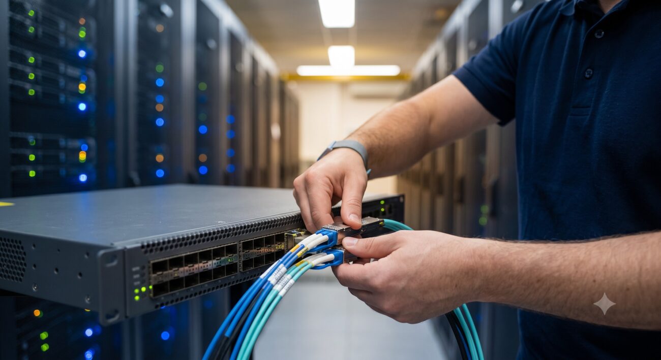
- A successful 4x25G breakout requires a compatible QSFP28 optical module, an MPO-to-4xLC breakout cable, and four SFP28 client modules. The host module (e.g., 100GBASE-SR4) installs in the switch port, while the breakout cable physically splits the multi-fiber MPO connection into four duplex LC connectors for the client devices . Both multi-mode (MMF) and single-mode (SMF) options exist, so ensure fiber type matches the modules.
- Q3: How do I configure 4x25G breakout mode using the Command Line Interface (CLI)?
- The general CLI method involves entering global configuration mode, navigating to the specific port, and applying a command to set the hardware profile to 4x25G. For example, on a Dell SONiC switch, the command is `interface breakout port slot/port mode 4x25G` . On a NETGEAR M4350, you would use `interface 1/0/43` followed by `hardware profile portmode 4x25G` . Always ensure the port is in a shutdown state before applying the change, as it is disruptive .
- Q4: Can I configure 4x25G breakout mode through a web interface (GUI)?
- Yes, many modern switches offer a GUI for breakout configuration, typically found under ‘Port Management’ or a similar menu. On a NETGEAR switch, you would navigate to ‘Switching > Ports > Expandable Port Configuration’, select the 100G port, and change the ‘Port Mode’ to 4x25G . For QNAP switches, the path is ‘System > Port Management > Port Breakout Configuration’ . After applying, the system will create four logical sub-interfaces that require speed and VLAN configuration.
- Q5: Are all 100G QSFP28 ports on a switch capable of supporting 4x25G breakout mode?
- No, breakout mode support is hardware-dependent and not universally available on all ports or switch models. It is crucial to consult the specific hardware data sheet for your switch. For instance, on the FS N5570-48S6C, only ports 49 and 52 support 4x25G breakout . Similarly, some Extreme Networks platforms limit breakout support to even-numbered ports . Always verify port capabilities before deployment.
- Q6: What is the difference between 4x10G and 4x25G breakout on a 100G port?
- The primary difference is the speed of the resulting logical interfaces: 10G vs. 25G. While both split a single 100G port into four links, 4x10G mode creates four 10Gbps interfaces, requiring SFP+ modules and a different breakout cable . 4x25G mode creates four 25Gbps interfaces using SFP28 modules. The choice depends on the speed capabilities of your downstream devices and the specific optical modules used.
- Q7: Does configuring 4x25G breakout mode impact data traffic, and what precautions should I take?
- Yes, enabling or changing breakout mode is a disruptive action that will cause the port and its associated links to go down and may require a reboot. The configuration change deletes the current port configuration and creates new logical interfaces . It is strongly recommended to schedule this maintenance during a planned downtime window. Always save the configuration after applying changes to ensure persistence after a reboot .
- Q8: What should I do if my 4x25G breakout ports are not coming online after configuration?
- Begin troubleshooting by verifying physical connections, module compatibility, and that the switch configuration matches the connected device speeds. Ensure auto-negotiation is disabled and the speed is manually set to 25G full-duplex on the new interfaces, especially when connecting to fixed-speed devices . Confirm the breakout cable is properly seated and that the correct fiber polarity is used. Finally, check the switch logs for any hardware errors or unsupported module warnings.

Leave a comment