
Introduction: The Invisible Threat to Network Integrity
In the realm of high-performance optical networking, the integrity of physical layer connections is paramount. Field data reveals that over 80% of intermittent network errors and performance degradation in high-density datacenter environments can be directly attributed to contaminated optical interfaces. For enterprise architects and network engineers, how to clean optical transceiver ports is not merely a maintenance chore but a critical operational discipline. Contamination, even at a microscopic level, induces high bit error rates (BER), increases optical return loss (ORL), and can permanently damage the fragile end-face of a transceiver, leading to costly hardware replacements and unplanned downtime. This definitive guide synthesizes industry best practices, IEEE standards, and field-proven methodologies to establish a robust cleaning protocol for your fiber optic infrastructure, ensuring optimal signal integrity and maximizing the Mean Time Between Failures (MTBF) of your optical assets.
Understanding the Contaminants and Their Quantified Impact
The Microscopic Culprits: Dust, Oils, and Static
The end-face of an optical connector is a precision surface. In a typical datacenter environment, airborne dust particles (ranging from 1 to 100 micrometers), skin oils, and isopropyl alcohol (IPA) residues from improper cleaning accumulate on the ferrule. When a contaminated connector is mated, the insertion loss (IL) can spike by 0.5 dB to 1.0 dB or more, directly reducing the power budget of the link. For a 100GBASE-LR4 link operating at 100 Gbps, a 1 dB increase in loss effectively reduces the link margin, making it susceptible to errors during power fluctuations.
Data-Driven Consequences
The quantitative impact is severe. A contaminated port can cause bit error rates (BER) to escalate from the acceptable threshold of 1e-12 to a catastrophic 1e-6, effectively rendering a link useless. Furthermore, the Optical Return Loss (ORL) can degrade from a healthy -45 dB to -20 dB or higher, introducing significant noise into the laser cavity, which can destabilize the transmission wavelength and shorten the lifespan of the Vertical Cavity Surface Emitting Laser (VCSEL) or Distributed Feedback (DFB) laser. Compliance with IEC 61300-3-35 standard is non-negotiable; it mandates a clean, defect-free end-face to ensure Telcordia GR-326-CORE reliability standards are met.
Hardware Topology: Standardized Connector Types and Their Susceptibility
The cleaning methodology is inherently linked to the connector’s physical architecture. The most common interfaces in modern telecom hardware include LC (Lucent Connector), SC (Subscriber Connector), and MPO/MTP (Multi-fiber Push-On). Their design dictates cleaning risk factors:
- LC Connectors: High-density, small form-factor. Their spring-loaded ferrule makes them susceptible to scratches if cleaned with abrasive tools. Cleaning requires precision, especially for 8-degree angled physical contact (APC) variants used for high-power and analog video applications.
- SC Connectors: Robust and square-shaped, easier to handle but prone to dust accumulation on the ferrule tip due to the exposed design when unmated.
- MPO/MTP Connectors: The highest risk category. With 12 or 24 fibers in a single ferrule, a single speck of dust on the guide pins or the array face can block multiple channels, degrading an entire 400GBASE-SR8 or 800G link.
Understanding these distinctions is crucial when evaluating how to clean optical transceiver ports effectively, as the mechanical tolerance and optical alignment precision of these interfaces differ significantly.
Step-by-Step Configuration Manual for Cleaning Optical Transceiver Ports
This protocol aligns with ISO 14644-1 cleanroom standards and provides a systematic approach to mitigating contamination risks.
Essential Tools and Consumables
- Dry Cleaning Kits: Reel-based cleaner (e.g., NTT-AT or 3M) for ferrule end-faces. These are optimal for field use as they provide a fresh, clean surface for each insertion.
- Wet Cleaning Kits: Isopropyl alcohol (IPA) wipes and swabs (≥99.9% purity) are essential. Note: IPA application must be minimal; excessive fluid can seep into the optical train, damaging internal components.
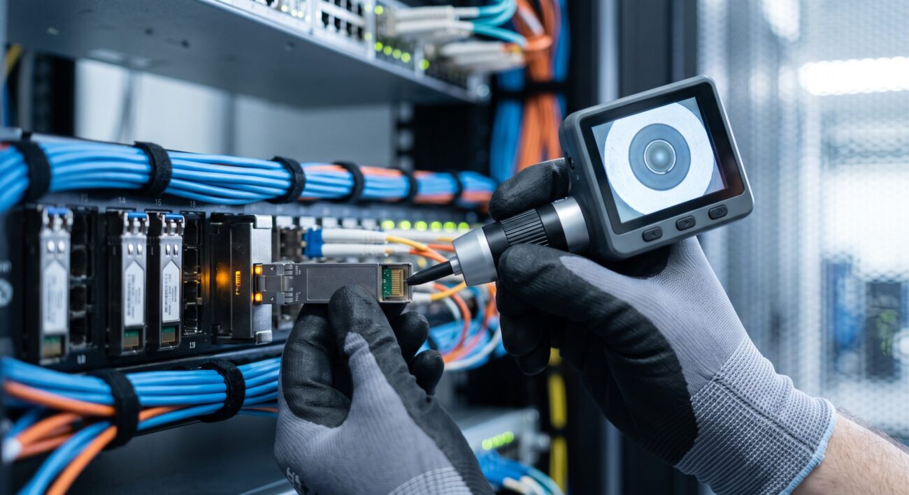
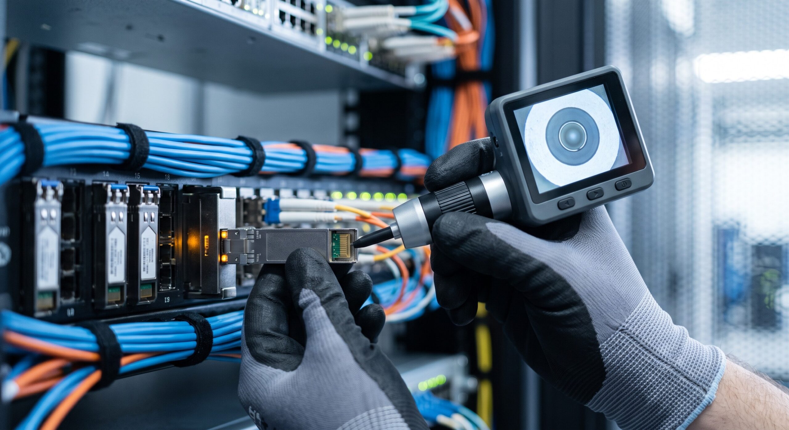
- Inspection Microscopes: A handheld optical or video probe (e.g., Fluke Networks or Viavi) with a 200x-400x magnification is mandatory. Cleaning without inspection is akin to configuring a network without a protocol analyzer.
- Compressed Air: Specifically designed for optical equipment, preventing static discharge.
The Five-Step Protocol
- Safety and Isolation: Always place the transceiver in a Safety Optical Switch or ensure the laser is turned off. Never inspect or clean a live port. Verify the device is Class 1 Laser Safety compliant to prevent eye damage.
- Inspection (First Pass): Use the video probe to inspect the end-face of the transceiver. If the contamination is isolated to a few spots, proceed to dry cleaning.
- Dry Cleaning: Insert the reel-based cleaner into the adapter port. Applying a consistent, light pressure, perform a single, unidirectional stroke. Do not scrub back and forth, as this grinds debris into the glass. For MPO connectors, use the specific multi-fiber cleaning tool.
- Inspection (Second Pass): Re-inspect the end-face. If the IEC Grade Criteria (e.g., Region A, B, C defect limits) are not met, proceed to wet cleaning.
- Wet Cleaning (If Required): Dampen a swab with IPA. Using a light, sweeping motion, clean the ferrule tip. Immediately follow with a dry swab to remove any residual fluid and dissolved contaminants. Final inspection must show no detectable particles or residues.
| Key Parameter | Technical Specification & Impact |
|---|---|
| Insertion Loss (IL) Increase | 0.5 dB to 1.0 dB per contaminated connection |
| Optical Return Loss (ORL) | Degrades from -45 dB to -20 dB |
| Bit Error Rate (BER) Escalation | Threshold degrades from 1e-12 to 1e-6 |
| Cleaning Process Duration | 45 seconds per connector (including inspection) |
Protocol Compliance and Standards Masterclass
IEC, ITU-T, and ANSI Standards
The engineering specs of optical cleaning are defined by global bodies. IEC 61300-3-35 is the core document defining the end-face geometry and defect tolerance. It categorizes scratches and pits into zones on the ferrule end-face. A Zone A scratch (core) must be absolutely free of defects, while Zone B (cladding) and Zone C (adhesive/ferrule) have specific size limits for allowable defects. Adherence to ITU-T G.650.1 also ensures that the polarization mode dispersion (PMD) and chromatic dispersion are not artificially induced by physical misalignment from contamination.
Furthermore, from a security and environmental perspective, RoHS compliance ensures that cleaning agents and materials do not contain hazardous substances, maintaining a green networking ethos. Cleaning procedures themselves must prevent the generation of static electricity that could damage sensitive CMOS transceiver chips. Grounding straps and anti-static mats are strongly recommended, especially in facilities with low-humidity environments.
Real-World Deployment and Field Topologies
High-Density Datacenter Scaling
In top-tier hyperscale datacenters, automated cleaning tools are integrated into patch-panel management. The robotic cleaning systems can clean an entire rack’s worth of QSFP-DD and OSFP transceivers without human intervention, reducing the Mean Time To Repair (MTTR) for fiber-related faults from 45 minutes to under 5 minutes. For edge networking deployments, where environmental dust is a higher risk, dust caps are the first line of defense. However, it’s critical to note that dust caps can also trap moisture and debris; they must be cleaned before re-insertion.
Case Study: Core Routing and Capacity Expansion
A major ISP experienced intermittent 10 Gbps link failures on a 12-fiber MPO trunk connecting a core Juniper PTX and Nokia 7750 router. The optical time-domain reflectometer (OTDR) showed a reflective event at the interface connector. After initial standard cleaning failed, a deeper extractive cleaning process using a specialized solvent was required to remove what was identified as a silicon-based lubricant from the factory. Post-cleaning, the optical power increased by 2.1 dBm, and the link’s forward error correction (FEC) margins returned to standard, eliminating packet drops. This highlighted the need for a tiered cleaning approach based on contamination type.

Conclusion: The Lifecycle Verdict and Operational Gains
Mastering how to clean optical transceiver ports is a fundamental pillar of network reliability. The quantified operational gains are clear: a well-maintained port delivers consistent throughput, minimized latency jitter, and extends the service lifetime of the transceiver, directly improving Total Cost of Ownership (TCO) by reducing premature hardware replacement. The process is neither trivial nor a one-size-fits-all procedure; it demands an understanding of the connector’s physical makeup, the contaminant’s nature, and a strict adherence to standardized inspection criteria. By embedding this cleaning protocol into your standard operational procedures, you ensure that your physical layer remains robust, ultimately safeguarding the performance of your entire network architecture against the invisible yet pervasive threat of contamination.
Remember, in the world of optical networking, a spec of dust can be as disruptive as a configuration error. Take the time to clean, inspect, and protect your optical transceiver ports, and your network will deliver the high-performance and reliability expected of modern carrier-grade and enterprise telecom hardware.

Leave a comment