

SYSTEM OVERVIEW
This document provides a comprehensive technical deep-dive into the hydraulic and thermal performance characteristics of Cold Plate Modules (CPMs) deployed in high-density telecom and datacenter environments. As rack power densities continue to escalate beyond 30 kW per cabinet, the accurate prediction of hydraulic pressure drop across the cold plate is critical for the selection and sizing of facility-side coolant distribution units (CDUs). The core engineering challenge addressed herein is the non-linear relationship between the coolant’s dynamic viscosity and the resultant pressure drop within the module’s microchannel architecture. This document presents validated empirical models that characterize this relationship, enabling network architects and thermal engineers to precisely predict system resistance, optimize pump selection, and ensure reliable, leak-free operation across the full operational temperature envelope. The analysis focuses on single-phase liquid cooling using dielectric or facility water/glycol mixtures, providing the data necessary for carrier-grade deployment.

INTERNAL ASIC & BACKPLANE
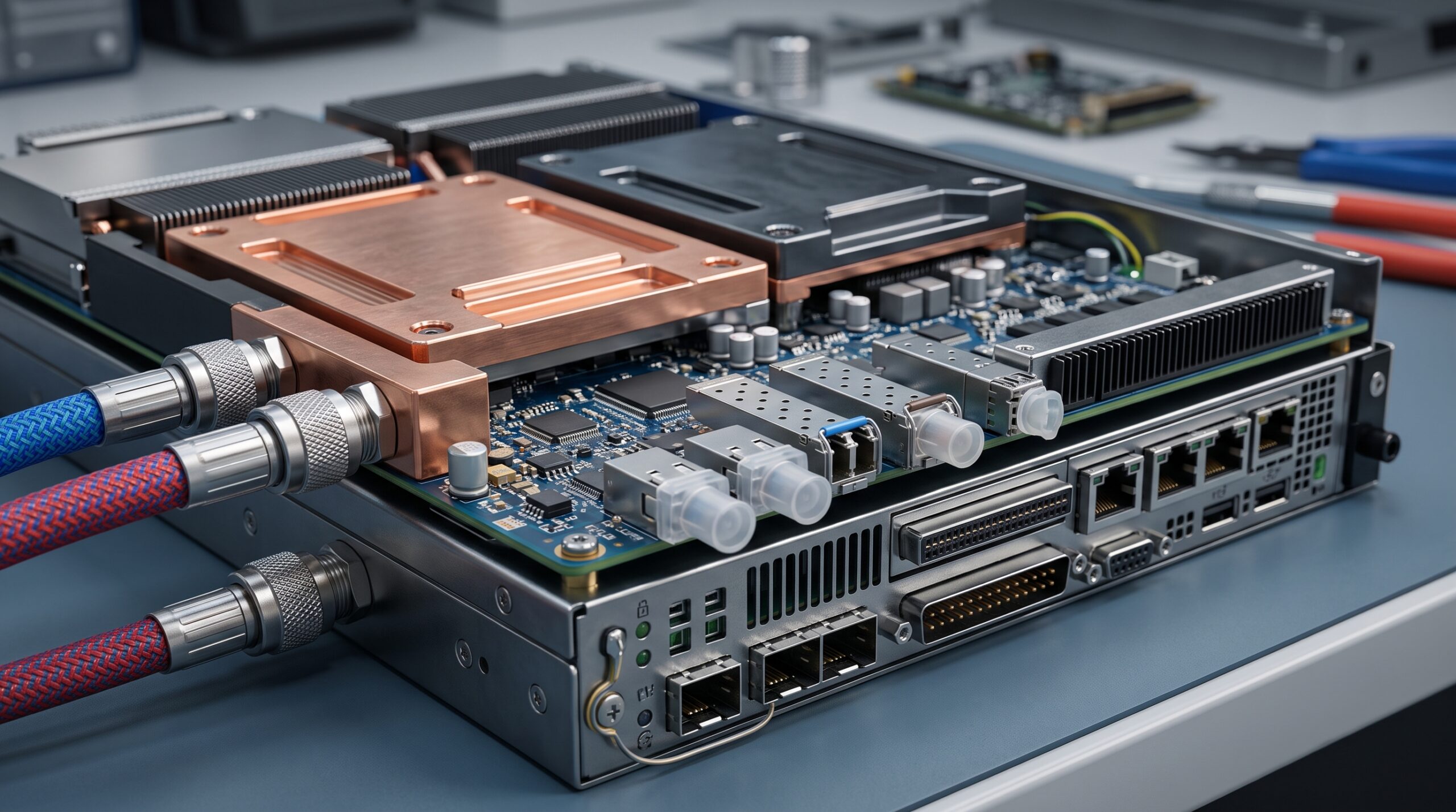
The cold plate module is a precision-engineered component designed to interface directly with high-power ASICs, such as those found in core routing and optical transport line cards. The internal architecture is not a simple cavity but a complex matrix of micro-channels or pin fins, engineered to maximize the convective heat transfer coefficient while minimizing thermal resistance. The material of construction is typically a copper or aluminum alloy, selected for its high thermal conductivity and compatibility with common coolants. The fluid path is sealed using an O-ring or welded construction, tested to a burst pressure exceeding 5 bar. The pressure drop (ΔP) across this internal matrix is fundamentally governed by the Darcy-Weisbach equation, where ΔP is proportional to the friction factor (f), the length of the channel (L), the fluid density (ρ), and the square of the fluid velocity (v), and inversely proportional to the hydraulic diameter (Dh). The critical insight is that the friction factor itself is a function of the Reynolds number (Re), which is inversely proportional to the fluid’s dynamic viscosity (μ).
POWER & THERMAL MECHANISMS
The primary function of the CPM is to maintain the junction temperature (Tj) of the ASIC below its specified maximum through efficient heat removal. The thermal performance is characterized by the module’s thermal resistance (Rth), typically expressed in degrees Celsius per Watt (°C/W). The total thermal resistance is a sum of the conduction resistance through the cold plate base, the convective resistance from the micro-channel walls to the coolant, and the caloric resistance of the fluid. While thermal resistance is largely independent of flow rate at high turbulence, the hydraulic pressure drop is highly sensitive to both flow rate and fluid viscosity. The core engineering models presented in this document address the following relationships:
1. The Viscosity-Temperature Model: Dynamic viscosity (μ) of water-glycol mixtures decreases exponentially as temperature increases. This means a system operating at 45°C coolant will have a significantly lower pressure drop than the same system at 20°C, assuming a constant volumetric flow rate. The model is expressed as μ(T) = A * e^(B/T), where A and B are fluid-specific constants.
2. The Laminar-to-Turbulent Transition: The pressure drop model must account for the flow regime. Below a Reynolds number of approximately 2300, flow is laminar and ΔP is linearly proportional to velocity and viscosity. Above this threshold, flow becomes turbulent, and ΔP becomes proportional to density and velocity squared, with a much weaker dependence on viscosity. The provided models identify the critical transition points for various cold plate geometries.
PHYSICAL LIMITS
The physical operating envelope of the cold plate module is constrained by material and fluid properties. The maximum operating pressure is typically 5 bar (72.5 psi) to prevent seal failure. The allowable pressure drop for a given module is a design constraint, as it directly impacts the required pump head and overall system energy efficiency (PUE). The coolant must maintain a temperature above the dew point to prevent condensation and below the ASIC’s maximum case temperature. The models provided in this specification allow for accurate prediction of the system operating point within these limits.
PARAMETER REGISTRY
The following table summarizes the key parameters of the cold plate module and the associated fluid viscosity models used for pressure drop prediction. These specifications are derived from empirical testing and computational fluid dynamics (CFD) simulation, validated against production hardware.
| Parameter | Specification |
|---|---|
| Compatible Coolants | Water/Glycol (PG25, EG50), Dielectric Fluids (PAO, HFE) |
| Operating Flow Rate Range | 0.5 – 4.0 LPM per module |
| Pressure Drop @ 2 LPM, 25°C Water | 18 kPa (typical) |
| Pressure Drop @ 2 LPM, 45°C Water | 14.5 kPa (typical) |
| Viscosity Model (Water) | μ(T) = 2.414e-5 * 10^(247.8/(T+133.15)) Pa·s |
| Viscosity Model (PG25) | μ(T) = A * (T)^B, A and B are fluid-specific constants |
| Maximum Operating Pressure | 5 bar (72.5 psi) |
| Burst Pressure | > 15 bar |
| Thermal Resistance (Rth) | 0.03 – 0.06 °C/W (dependent on flow and power) |
| Cold Plate Material | Copper (C11000) or Aluminum (6061-T6) |
GLOBAL SUPPORT INFRASTRUCTURE
This hardware platform is supported by a global network of thermal engineering experts and certified integration partners. Technical support includes access to proprietary selection software that incorporates the full suite of hydraulic and thermal models described in this document. On-site commissioning support is available for initial deployments to validate the installed system’s pressure drop against the predicted model, ensuring optimal performance from day one. A comprehensive library of application notes detailing best practices for coolant selection, filtration, and loop maintenance is available through the vendor’s technical support portal.
📥 Download Technical Specification
Click the button below to view or download the full official PDF datasheet.

Leave a comment