
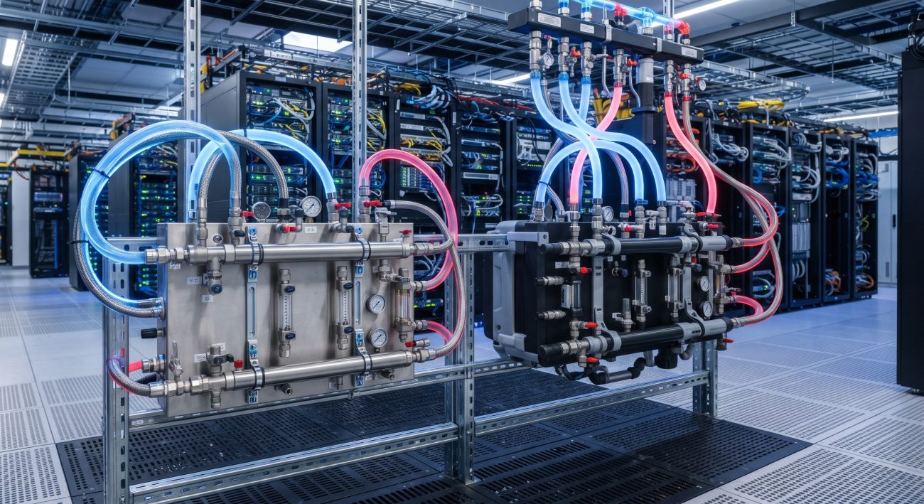
SLA Demands in the Megawatt Era: Why Manifold Material Determines Uptime
As AI accelerator racks push beyond 100 kW and megawatt-scale data halls become the norm, the liquid cooling manifold has evolved from a passive plumbing accessory into a mission-critical hydraulic backbone . The material selection—stainless steel versus engineered polymer—directly governs mean time between failures (MTBF), thermal stability under fault conditions, and the long-term operational expenditure profile of the entire facility. This analysis delivers a carrier-grade reliability assessment grounded in ASHRAE guidelines, OCP specifications, and field-validated deployment data.
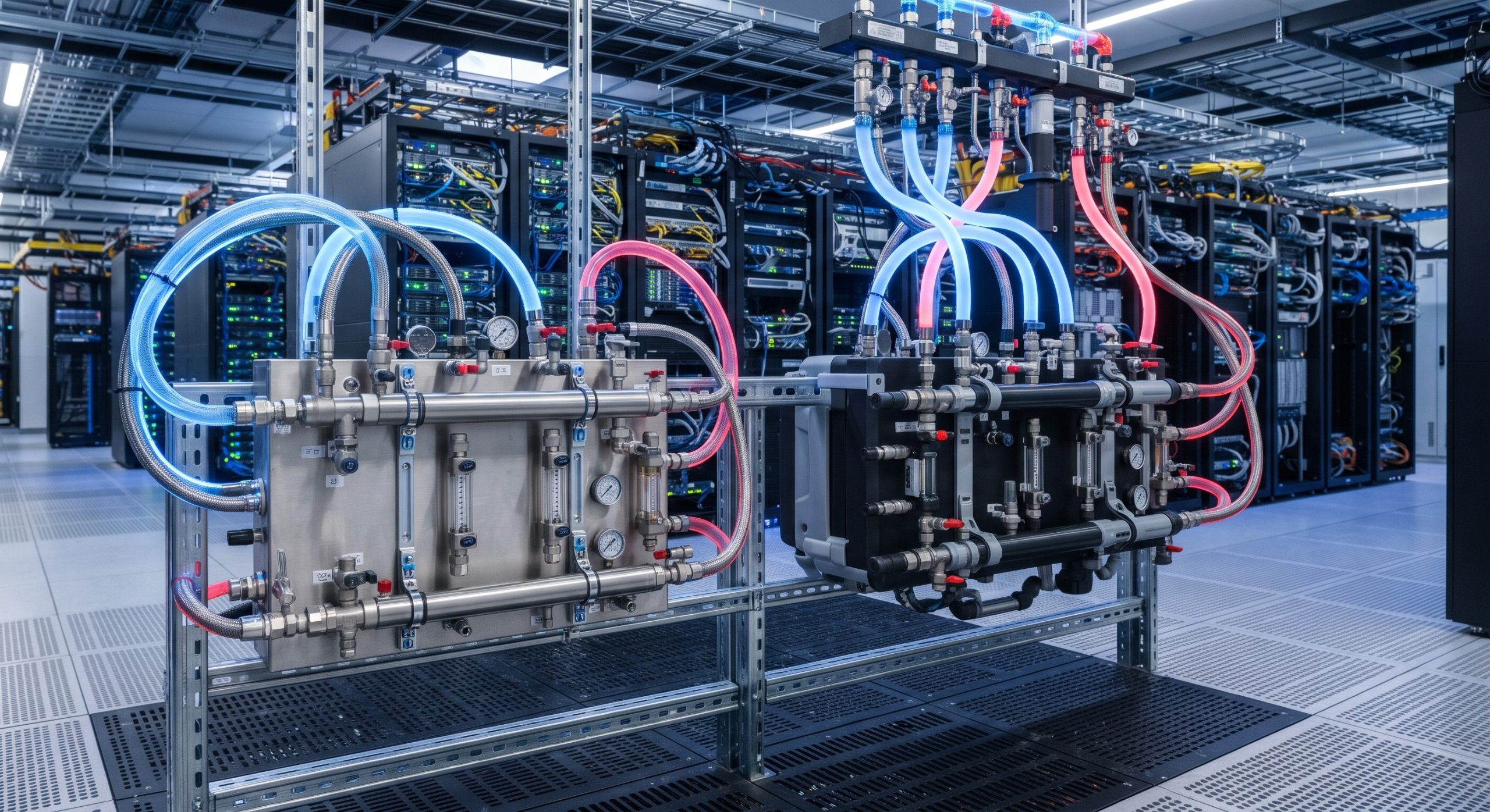
Dual-Engine Failover Architecture and Material-Level Redundancy
In a carrier-grade liquid cooling loop, redundancy is engineered at both the system and component levels. The manifold module must maintain hydraulic integrity during pump failover, thermal transient events, and maintenance isolation. Stainless steel manifolds—typically 304/304L or 316/316L—provide a fundamental reliability advantage through dimensional stability under thermal cycling. When fluid temperatures spike from nominal 40°C to 60°C or even 90°C under fault conditions, stainless steel exhibits negligible creep deformation, preserving joint integrity and preventing leak paths at welded or compression interfaces .
Polymer manifolds, particularly PVDF and polypropylene, offer compelling weight and corrosion advantages, yet their viscoelastic nature introduces a reliability trade-off. At sustained elevated temperatures, thermoplastics are susceptible to creep and stress relaxation, which can reduce clamp load at gasket interfaces and accelerate fatigue at branch connections . For megawatt-class deployments where MTBF targets exceed 100,000 hours, this behavior demands rigorous derating and validation beyond standard pressure-test protocols.
Thermal Expansion and Joint Integrity Under Cycling Loads
Stainless steel’s coefficient of thermal expansion (CTE ≈ 16–17 µm/m·K) is significantly lower than that of polypropylene (CTE ≈ 100–180 µm/m·K). In a 2-meter manifold subjected to a 40°C delta, the differential expansion translates to millimeters of displacement—enough to impose substantial shear stress on elastomeric seals and quick-disconnect couplings . Stainless steel’s dimensional stability minimizes this risk, whereas polymer systems require carefully engineered expansion loops or sliding supports to prevent premature seal failure.
MTBF Metrics: Quantifying Material Reliability
Mean time between failures for manifold modules is not a single datasheet value; it is a composite of material corrosion resistance, weld/fusion joint integrity, seal compatibility, and particulate shedding behavior. The following matrix synthesizes reliability-relevant parameters from industry specifications and field data.
| Reliability Parameter | Stainless Steel (304/316L) | Engineered Polymer (PVDF/PP) |
|---|---|---|
| Typical Design Life | 15–25 years | 10–15 years (application-dependent) |
| Thermal Expansion (CTE) | ~16–17 µm/m·K | ~100–180 µm/m·K (PP); ~80–120 µm/m·K (PVDF) |
| Max Continuous Fluid Temp | Up to 120°C+ | Typically 80–90°C (derated for pressure) |
| Corrosion Resistance (PG25) | Excellent (autopassivating oxide layer) | Excellent (PVDF); Not recommended (PP per ASHRAE) |
| Creep Resistance Under Load | Superior | Moderate; temperature-dependent |
| Burst Pressure (typical) | >25 MPa (small diameter) | Application-specific; lower than steel |
| OCP Ecosystem Recognition | Mature; broad UQD/QD compatibility | Emerging; PVDF manifold OCP Inspired™ |
| Weight (relative) | Baseline | Up to 75% lighter |
Corrosion and Coolant Compatibility: The Hidden MTBF Driver
Modern coolant formulations—typically 25% propylene glycol (PG25) with corrosion inhibitors and biocides—present a chemically aggressive environment over a 10-year design life. Stainless steel’s autopassivating chromium oxide layer provides continuous corrosion protection that re-forms if locally damaged, offering a well-characterized corrosion rate of <0.1 mm/year under typical TCS loop conditions .
ASHRAE’s Liquid Cooling Guidelines notably do not list polypropylene as a recommended material for high-purity Technology Cooling System loops, citing risks of polymer degradation and additive leaching that can foul microchannel cold plates . PVDF, a fluoropolymer, demonstrates superior chemical resistance and has achieved OCP Inspired™ recognition for in-rack manifold applications, signaling growing ecosystem acceptance for qualified polymer solutions in specific deployment contexts .
Mission-Critical Deployments: Field Evidence and Qualification Status
The qualification landscape reveals a bifurcated market. Stainless steel manifolds dominate carrier-grade and colocation environments where standardized quality assurance across multi-site rollouts is paramount. Production standards, welding qualifications (per ASME Section IX), and pressure-test protocols provide consistent, auditable quality checkpoints that hyperscalers demand . Commercial off-the-shelf stainless steel rack manifolds are rated for 12 bar proof pressure with recommended operating pressures around 2 bar and temperature ranges spanning -20°C to +120°C .
Polymer manifold adoption is advancing through live data center validations. LG U+’s AI DC Testbed in South Korea deployed a PVDF in-rack manifold supporting a 100 kW rack with PG25 coolant, citing corrosion-free operation, reduced pumping effort, and lower embodied carbon as primary drivers . GF’s PVDF manifold has undergone multiple proof-of-concept deployments across the Americas, Europe, and Asia-Pacific, with each unit receiving a 100% pressure test before shipment . These deployments demonstrate viability but do not yet match the multi-decade field history of stainless steel in mission-critical fluid service.
Hydraulic Performance Under Redundancy Scenarios
Computational fluid dynamics modeling of a 132 kW/rack reference design reveals that polymer manifold configurations can achieve approximately 19% lower total system pressure loss compared to stainless steel equivalents, primarily due to smoother internal geometry and optimized flow paths . This hydraulic advantage translates to reduced pump energy consumption—a meaningful OPEX benefit at megawatt scale—but must be weighed against the reliability premiums discussed above.

Final Assessment: Matching Material to Mission Profile
The stainless steel versus polymer decision is not binary; it is a risk-weighted engineering trade-off. For carrier-grade, multi-tenant, and fault-intolerant megawatt deployments, stainless steel manifolds deliver the MTBF certainty, thermal stability, and supply-chain maturity that SLA commitments demand. Their resistance to creep, proven corrosion performance with glycol coolants, and compatibility with OCP-standard quick-disconnects make them the conservative, audit-friendly choice for 99.999% uptime targets.
Engineered polymer manifolds—particularly PVDF—offer compelling advantages in weight reduction (up to 75% lighter), corrosion immunity, and lower embodied carbon, with OCP recognition signaling maturing ecosystem support . They are best suited for retrofits, modular edge deployments, and organizations with aggressive sustainability mandates where the coolant chemistry is rigorously controlled and the thermal envelope is tightly bounded. For megawatt-scale core facilities, the prudent path is to qualify polymer manifolds through extended field trials under real thermal cycling before committing them to primary cooling loops.
Leave a comment