

SYSTEM OVERVIEW
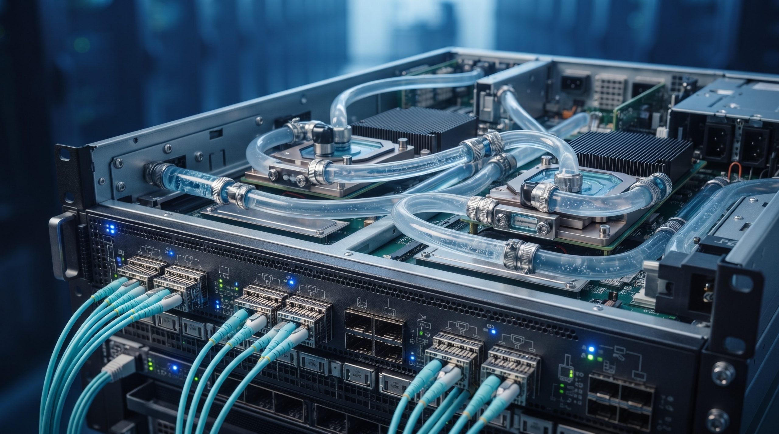
The High-Bandwidth Liquid-Cooled Switch Internal Secondary Hose Schematics solution represents a paradigm shift in thermal management for next-generation, high-density switching platforms. As switching capacities scale beyond 51.2 Tbps per rack unit, conventional air-cooling architectures become physically and economically unviable. This document provides an exhaustive technical deep-dive into the internal secondary hose assembly, the critical fluid-bearing subsystem that bridges the facility’s primary coolant loop to the sensitive silicon photonics and ASIC cold plates within the chassis. The secondary hose network is engineered as an integrated, factory-sealed, and serviceable manifold system designed to deliver dielectric coolant at precise flow rates and temperatures, ensuring optimal junction temperatures for high-bandwidth switching silicon under full line-rate load conditions.

INTERNAL ASIC & BACKPLANE
The core of the switching platform is a liquid-cooled, multi-die package that integrates the high-bandwidth forwarding ASIC with its high-speed SerDes I/O. The internal secondary hose assembly is directly coupled to the ASIC cold plate through a set of redundant, quick-disconnect (QD) fittings. These fittings are designed for zero-spill maintenance and are rated for a minimum of 10,000 mating cycles. The hose routing is meticulously engineered to minimize pressure drop and avoid electromagnetic interference with the backplane traces. The secondary loop operates at a nominal pressure of 2.5 bar and is compatible with a range of facility-provided coolants, including PG25 and specialized dielectric fluids. Each hose is constructed from a multi-layer polymer blend with an internal liner that prevents permeation and leaching, ensuring long-term fluid integrity and system reliability.
POWER & THERMAL MECHANISMS
The thermal management subsystem is a closed-loop, negative-pressure design. A variable-speed pump within the chassis drives the secondary coolant through the manifold, distributing flow to individual cold plates via the internal secondary hoses. The hose schematics incorporate a series of inline sensors, including flow meters, temperature probes (RTD), and pressure transducers, providing real-time telemetry to the chassis management controller (CMC). This data is used to dynamically modulate pump speed and valve positions to maintain optimal coolant delta-T across the ASIC, even under fluctuating ambient conditions. The system is designed to dissipate up to 1.5 kW per switching ASIC, with a total chassis heat rejection capability of 15 kW. The power shelf is isolated from the liquid loop and utilizes a separate air-cooled path to ensure electrical safety and redundancy.
PHYSICAL LIMITS
The internal secondary hose assembly is designed to operate within a narrow physical envelope to maximize port density and serviceability. The minimum bend radius of the hose is 15mm, and the assembly is qualified for operation in ambient temperatures ranging from 5°C to 45°C. The coolant supply temperature can range from 15°C to 40°C, with a maximum operating pressure of 4 bar. The hose material is rated for a 15-year service life and is resistant to UV degradation and ozone cracking. All wetted materials are compliant with RoHS and REACH directives.
PARAMETER REGISTRY
| Parameter | Specification |
|---|---|
| Hose Material | Multi-layer polymer blend with permeation barrier |
| Operating Pressure | Nominal 2.5 bar; Maximum 4 bar |
| Supply Temperature Range | 15°C to 40°C (Coolant) |
| Flow Rate per ASIC | Up to 8 L/min (Adjustable) |
| Quick Disconnect Fittings | Zero-spill, 10,000 mating cycles |
| Coolant Compatibility | PG25, Dielectric Fluids |
| Maximum Heat Dissipation | 1.5 kW per ASIC / 15 kW per Chassis |
| Telemetry | Flow, Temperature, Pressure via CMC |
| Service Life | 15 Years |
| Compliance | RoHS, REACH |
GLOBAL SUPPORT INFRASTRUCTURE
Our global support infrastructure is structured to ensure maximum uptime for liquid-cooled deployments. We offer a comprehensive suite of services, including factory-trained field engineers for hose and manifold replacements, a 24/7 technical assistance center (TAC) with dedicated liquid-cooling specialists, and a global spare parts logistics network. Advanced replacement units for the entire secondary hose assembly are available within 4-hour service level agreements (SLAs) in major metropolitan areas. Furthermore, our predictive maintenance platform leverages the telemetry data from the inline sensors to proactively schedule maintenance and prevent unplanned downtime. All service procedures are documented in the official Systems Engineering Technical Reference Manual.
📥 Download Technical Specification
Click the button below to view or download the full official PDF datasheet.
Leave a comment