

EXECUTIVE SUMMARY
As the telecommunications industry transitions toward higher-density, always-on infrastructure, the resilience of the power subsystem has become a critical determinant of network reliability. The Intelligent Battery Management System (BMS) represents a paradigm shift from passive battery backup to active, predictive power management. Engineered specifically for carrier-grade central offices, edge computing nodes, and 5G distributed units (DUs), this BMS hardware platform integrates real-time cell monitoring, adaptive charge/discharge algorithms, and proactive fault prediction to extend battery service life by up to 40% while ensuring zero-downtime transitions during grid anomalies. Designed around a modular, hot-swappable architecture, the BMS offers granular visibility into each battery string’s State of Health (SoH), State of Charge (SoC), and internal resistance, delivering actionable telemetry to Network Operations Centers (NOCs) via standard SNMP or Modbus protocols. This document provides a comprehensive technical overview, hardware specifications, and compliance benchmarks for the intelligent BMS platform, establishing it as the foundational element for future-proof, energy-resilient telecom deployments.

ARCHITECTURE & CHASSIS DESIGN
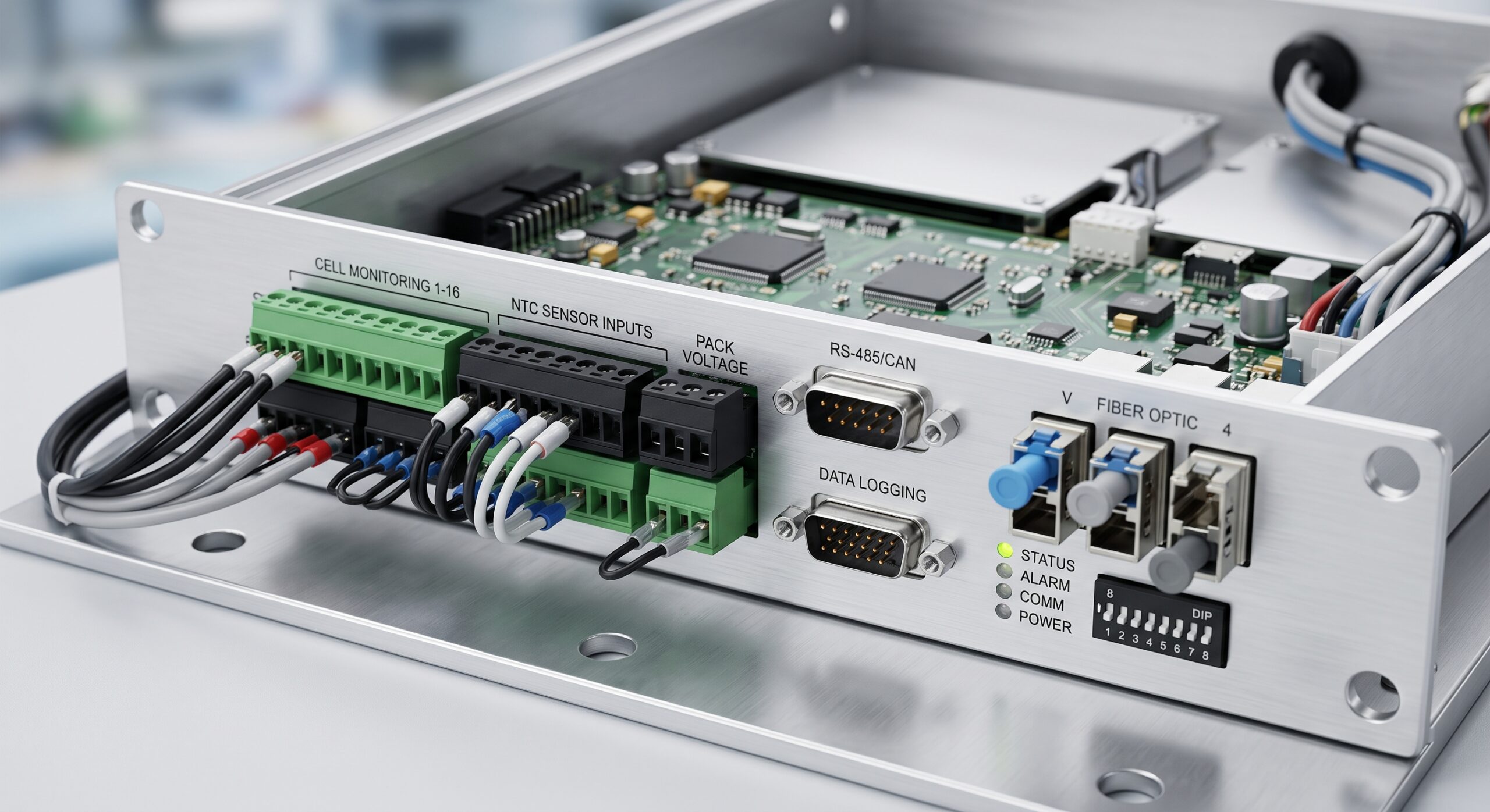
The Intelligent BMS hardware architecture is predicated on a distributed master-slave control plane that decouples monitoring from actuation for enhanced redundancy and throughput. The central Master Control Unit (MCU), housed within a rugged 2RU chassis, acts as the system’s primary orchestrator, managing communication with up to 128 subordinate Battery Monitoring Modules (BMMs) via an isolated, high-speed CAN-FD bus. The chassis is engineered with a dedicated rear backplane that segregates high-current power paths from low-voltage signaling, eliminating electromagnetic interference (EMI) and ensuring stable data acquisition during transient load events.
A key design differentiator is the implementation of a dual-redundant power supply unit (PSU) bay, supporting either AC (100-240V) or DC (-48V) inputs with automatic failover and load-sharing capabilities. The front faceplate hosts a multi-functional LCD panel for local status interrogation alongside tri-color LED indicators for rapid health assessment: Green (Nominal), Amber (Warning), and Red (Critical). The chassis utilizes forced-air convection cooling, guided by five variable-speed fan trays that modulate airflow based on internal thermistor readings, ensuring operational stability across a temperature range of -5°C to +55°C. The mechanical design adheres to ETSI 300 019 standards, ensuring compatibility with standard 19-inch or 23-inch mounting rails in diverse field environments.
HARDWARE FEATURES
The core hardware intelligence lies within each BMM, a compact, low-profile board specifically designed for top-terminal or front-terminal battery racks. Each BMM integrates a high-precision 24-bit analog-to-digital converter (ADC) capable of measuring voltage with an accuracy of ±1 mV and current via Hall-effect sensors with ±0.5% precision. Crucial features include:
– **Passive Balancing Technology:** The BMS employs a proprietary resistor-based passive balancing circuit that dissipates excess energy from higher-voltage cells, activated via pulse-width modulation (PWM) control to minimize heat generation while maintaining string equilibrium.
– **Built-In Isolation Monitoring:** A dedicated insulation resistance monitoring circuit continuously assesses the integrity of the DC bus to ground, triggering alarms when resistance drops below the configurable threshold (default: 1 MOhm), thereby preventing potential arcing and safety hazards.
– **Onboard Data Logging:** Each BMM is equipped with 8MB of non-volatile flash memory, capable of storing event logs and performance trend data for up to 90 days, ensuring that root-cause analysis is possible even during communication link failures.
– **Fast-Charge Enablement:** The BMS hardware supports an adaptive charging profile that allows for a controlled, high-current bulk charge phase, reducing total recharge time by up to 35% compared to traditional taper-charge methods, provided the external rectifier system is sized accordingly.
COMPLIANCE & STANDARDS
The Intelligent BMS platform has been rigorously tested and validated against a comprehensive suite of international standards to ensure interoperability and safety across global telecom territories. This commitment to compliance simplifies regulatory approval for network operators and reduces time-to-market for new infrastructure rollouts.
– **Safety Standards:** UL 1973 (for batteries), IEC 62368-1 (Audio/Video/ICT Equipment), and IEC 60950-22 (Equipment for Outdoor Installation).
– **Electromagnetic Compatibility (EMC):** FCC Part 15 Subpart B (Class A), EN 55032, and EN 55024, ensuring immunity against electrostatic discharge and surge events typical in industrial environments.
– **Environmental Compliance:** RoHS and REACH compliant. Additionally, the system meets the stringent Shock and Vibration requirements of GR-63-CORE and carries an IP20 rating for the chassis (higher IP protection available on request for specific modules).
– **Telecom Network Standards:** Fully interoperable with TL 9000 quality management frameworks, supporting standardized alarm reporting per ITU-T M.3100 and X.733.
TECHNICAL SPECIFICATIONS
The hardware specifications below define the operational envelope, capacity, and physical characteristics of the Intelligent BMS. All metrics are based on a +25°C ambient temperature unless otherwise specified.
| Parameter | Specification |
|---|---|
| System Model | BMS-MC-128 / BMS-MC-256-PRO |
| Form Factor | 2RU Rack-Mountable (19-inch / 23-inch) |
| Supported Battery Strings | Up to 128 Parallel Strings |
| Measurement Accuracy (Voltage) | ± 1 mV (24-bit ADC) |
| Measurement Accuracy (Current) | ± 0.5% of Reading via Hall Effect |
| Max System Voltage | 750 V DC (Battery Bus) |
| Communication Protocols | SNMP v2c/v3, Modbus TCP/RTU, CAN-FD |
| Internal Balancing Current | Up to 1.5A (Passive per Cell) |
| Power Consumption | ≤ 25W (Standalone), ≤ 45W (Full Load) |
| Operating Temperature | -5°C to +55°C (15°F to 131°F) |
| Storage Temperature | -40°C to +85°C (-40°F to 185°F) |
| Relative Humidity | 5% to 95% (Non-Condensing) |
| MTBF (Telecordia SR-332) | > 450,000 Hours |
| Safety Certifications | UL 1973, IEC 62368-1, IEC 60950-22 |
ORDERING OPTIONS
The Intelligent BMS is available in three distinct factory-configured base SKUs to address varying site capacities and integration requirements. Additionally, a comprehensive menu of spares and accessories allows for deep customization.
– **BMS-MC-128:** Standard Master Control Unit with integrated Web UI, supporting up to 64 BMMs. Equipped with 1x AC PSU and 1x DC PSU.
– **BMS-MC-256-PRO:** High-Capacity Master Control Unit supporting up to 128 BMMs. Includes dual AC PSUs, high-performance Cortex-A7 CPU, and 4GB eMMC for extended data storage.
– **BMM-CU-12:** Universal Battery Monitoring Module designed for 2V, 6V, or 12V individual cells, compatible with VRLA, LiFePO4, and Ni-Cd battery chemistries.
– **Spares & Accessories:** Temperature Sensor Probes (BMS-TS-04), Current Shunt Modules (BMS-SHUNT-1KA), Extended Chassis Mounting Brackets, and 5m CAN-FD Trunk Cables.
📥 Download Technical Specification
Click the button below to view or download the full official PDF datasheet.

Leave a comment