

EXECUTIVE SUMMARY
This document serves as the definitive technical reference for the deployment and operational utilization of precision optical attenuators within carrier-grade fiber optic networks. As next-generation coherent optics and dense wavelength division multiplexing (DWDM) systems push the boundaries of link budgets, the precise management of optical power levels is paramount to preserving signal integrity, maximizing receiver dynamic range, and ensuring system longevity. The Optical Attenuator Application Guidelines outlined in this datasheet codify best practices for static and dynamic attenuation, covering insertion loss budgeting, connector interface compliance, and environmental resilience. These guidelines are designed to harmonize hardware capabilities with the rigorous performance demands of modern optical transport networks, from metro rings to ultra-long-haul submarine links.

ARCHITECTURE & CHASSIS DESIGN
The recommended deployment architecture for optical attenuation adheres to a hierarchical chassis and panel-based integration model, supporting both modular rack-mounted chassis systems (1RU to 5RU form factors) and compact standalone in-line attenuation modules. The system design is predicated on a passive, wavelength-independent optical pathway that maintains low polarization-dependent loss (PDL) and minimal insertion loss variation across the entire C-band and L-band transmission windows. For high-density central office applications, a rear-access chassis design is available that facilitates front-facing patching and attenuation adjustments, enabling technicians to perform power-level tuning without disrupting adjacent fiber terminations. The architecture supports a mixed complement of fixed-value attenuators, variable optical attenuators (VOAs), and loopback attenuation modules, ensuring full flexibility for link conditioning, receiver overload protection, and equalization of channel power.
HARDWARE FEATURES
The attenuation hardware portfolio is engineered with precision, leveraging micro-optic and MEMS-based technologies to deliver superior optical performance and operational stability. Key features include:
– WIDE ATTENUATION RANGE: 0 to 30 dB for fixed attenuators and 0 to 40 dB for VOA variants, with 0.1 dB incremental resolution.
– LOW INSERTION LOSS: Base insertion loss of ≤ 1.0 dB at 1550 nm, with premium grades achieving ≤ 0.5 dB.
– HIGH RETURN LOSS: ≥ 55 dB for UPC connectors and ≥ 65 dB for APC connectors, minimizing coherent reflections.
– EXCEPTIONAL PDL: ≤ 0.15 dB across the specified operating wavelength range, ensuring negligible impact on polarization-multiplexed signals.
– WAVELENGTH DEPENDENCE: Attenuation variation of less than ±0.5 dB from 1525 nm to 1625 nm, preserving channel uniformity.
– DURABLE CONNECTOR INTERFACES: Factory-terminated with high-precision zirconia ferrule connectors (LC, SC, and FC types), compliant with IEC 61754-20 and Telcordia GR-326-CORE standards.
– ENHANCED RELIABILITY: Hermetically sealed optical path for fixed attenuators and hermetically packaged MEMS components for VOAs, ensuring operation in non-temperature-controlled environments from -5°C to +70°C.
COMPLIANCE & STANDARDS
All attenuation solutions referenced in this guideline are fully certified and compliant with the following international telecommunication and environmental standards, confirming their suitability for global network deployments:
– TELCORDIA GR-910-CORE: Generic Requirements for Fixed Optical Attenuators.
– TELCORDIA GR-2892-CORE: Reliability Assurance for Optical Components.
– IEC 61300-2-1: Environmental tests for optical components (Damp heat, dry heat, and temperature cycling).
– IEC 60825-1: Laser safety compliance, Class 1M laser product designation.
– ROHS & REACH: Fully compliant with EU directives on hazardous substances and chemical registration.
– ITU-T G.671 & G.681: Transmission characteristics of optical components.
– GR-1089-CORE: Electromagnetic compatibility requirements for central office equipment.
TECHNICAL SPECIFICATIONS
| Parameter | Specification |
|---|---|
| Form Factor | 1RU / 2RU Chassis, In-Line Module, or Pluggable |
| Attenuation Range (Fixed) | 0 – 30 dB (std. values: 1, 2, 3, 5, 6, 7, 8, 10, 15, 20, 25, 30 dB) |
| Attenuation Range (VOA) | 0 – 40 dB (0.1 dB steps) |
| Operating Wavelength | 1525 nm – 1625 nm (C- & L-band) |
| Insertion Loss (Typ.) | ≤ 1.0 dB (0.5 dB Premium) |
| Return Loss (UPC/APC) | ≥ 55 dB / ≥ 65 dB |
| Polarization Dependent Loss (PDL) | ≤ 0.15 dB |
| Wavelength Dependent Loss (WDL) | ≤ ±0.5 dB |
| Optical Power Handling | ≤ 500 mW (continuous) |
| Connector Interface | LC, SC, FC (UPC or APC polish) |
| Operating Temperature | -5°C to +70°C (Extended: -40°C to +85°C) |
| Storage Temperature | -40°C to +85°C |
| Relative Humidity (non-condensing) | 5% to 95% |
| MTBF (Predicted) | > 1,500,000 hours (Telcordia SR-332) |
| Package Style | Rackmount, Panel-Mount, or In-Line Pigtail |
ORDERING OPTIONS
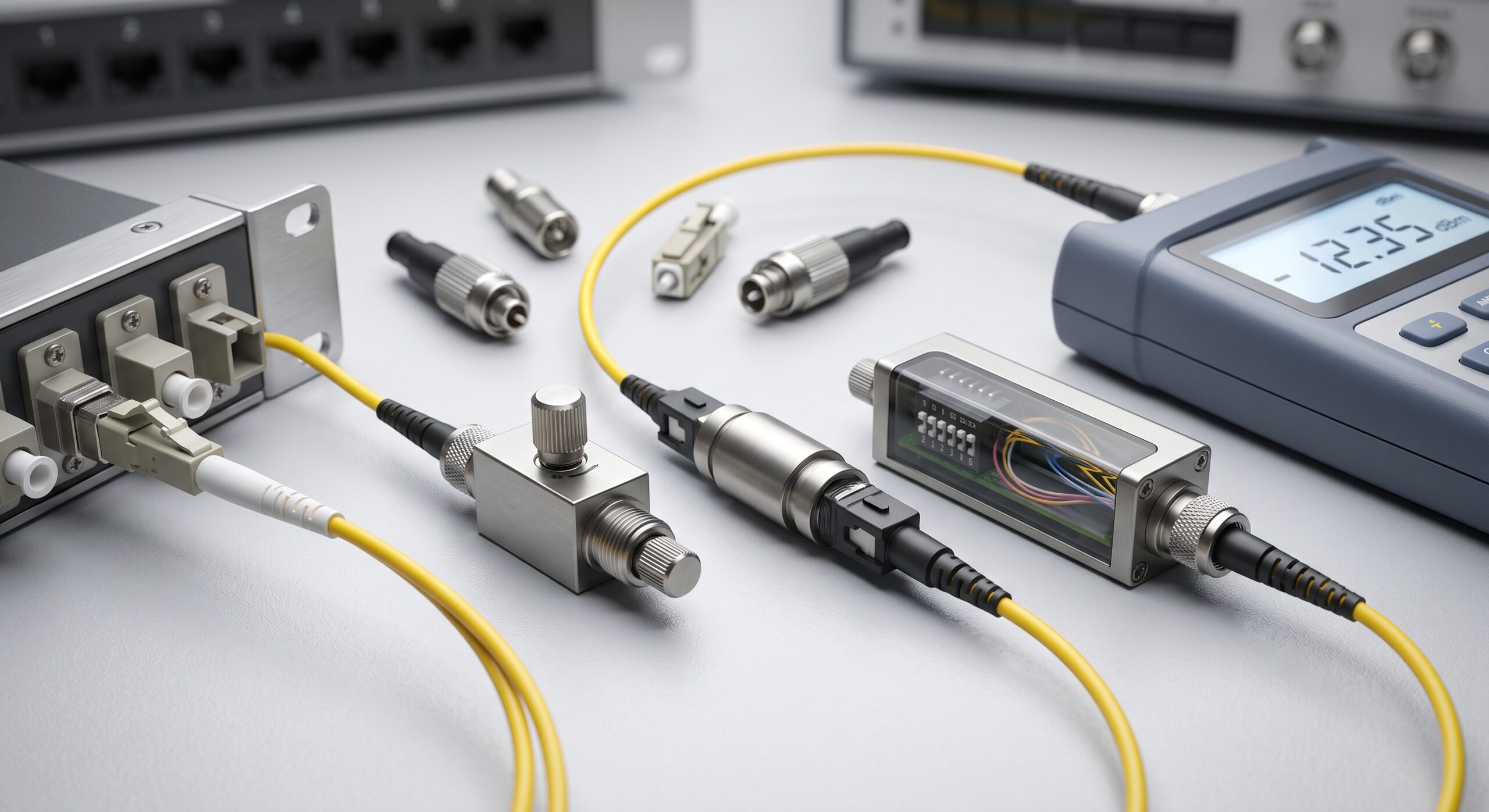
The Optical Attenuator Application Guidelines support a comprehensive ordering structure, enabling precise customization for diverse network scenarios. Fixed attenuators are available in the following standard attenuation values: 1, 2, 3, 5, 6, 7, 8, 10, 15, 20, 25, and 30 dB, with an accuracy of ±0.5 dB. Variable optical attenuators (VOAs) can be ordered as manual-turn screw-type devices, or as motorized, digitally controlled units for remote management via SNMP, including support for closed-loop power control. Additionally, pluggable attenuation modules for XFP, SFP+, and QSFP transceivers are available for per-port conditioning. All variants support a selection of industry-standard connector interfaces and polish types (UPC/APC), along with customized pigtail lengths (standard 1.5m to 5m). For turnkey deployment, our engineering services provide factory pre-testing and matched-pair attenuation sets to ensure optimized link budgets, reducing field commissioning time.
📥 Download Technical Specification
Click the button below to view or download the full official PDF datasheet.

Leave a comment