

RUGGEDIZED TELECOM INFRASTRUCTURE APPLICATION NOTE
EXECUTIVE OVERVIEW
This document serves as the definitive technical reference for the environmental specifications governing the deployment of the Industrial Ethernet Switch series. Designed to operate in the most unforgiving physical conditions, this equipment transcends standard commercial-grade limitations, delivering deterministic performance across extreme thermal ranges, high-humidity environments, and electrically noisy industrial settings. This application note details the mechanical, climatic, and electromagnetic compliance parameters essential for network architects, systems integrators, and facility engineers to ensure seamless long-term reliability in critical infrastructure.

RUGGEDIZED DESIGN PHILOSOPHY
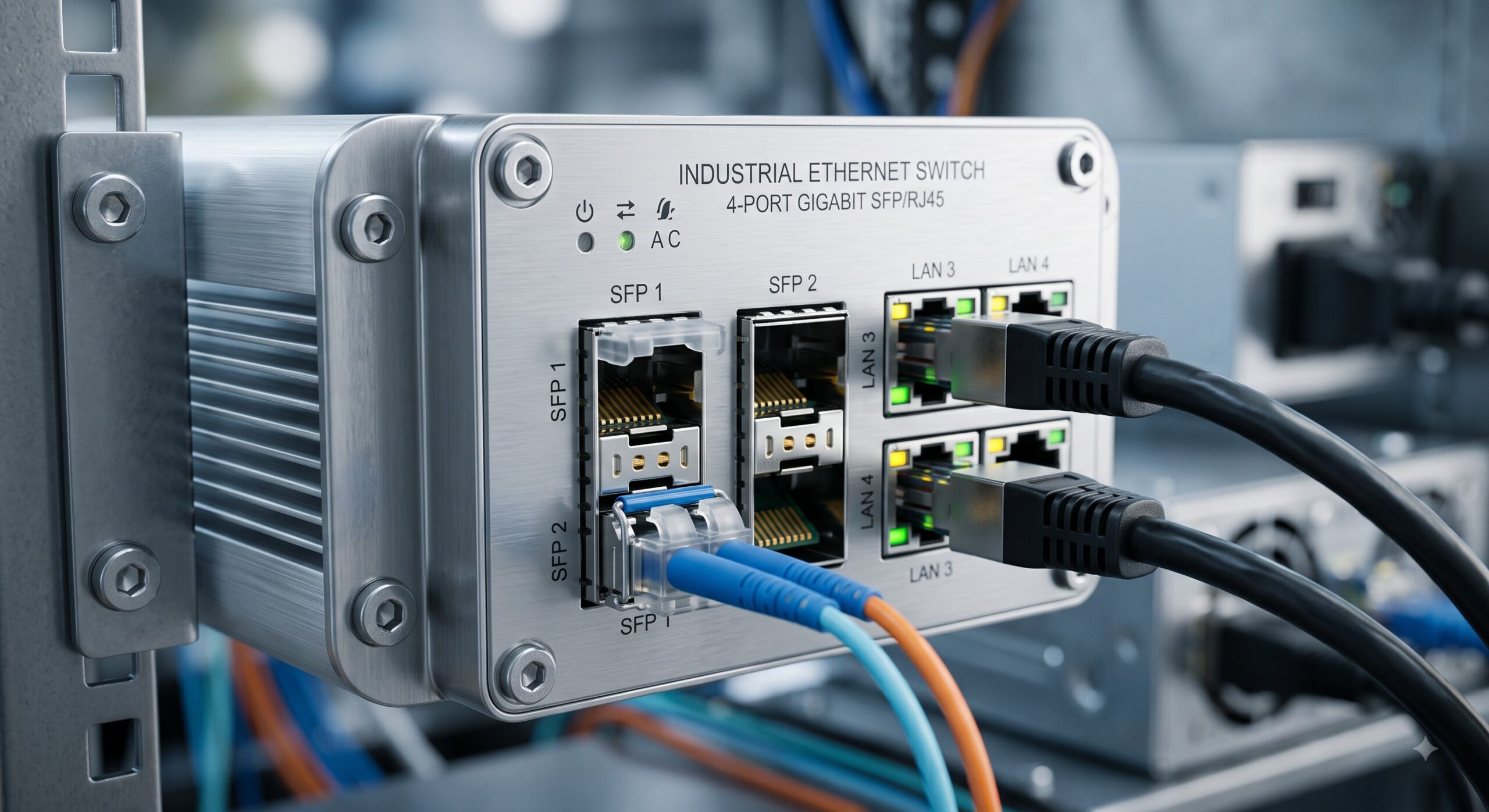
The Industrial Ethernet Switch is engineered from the ground up for harsh environments. Unlike enterprise-grade equipment confined to climate-controlled data centers, this platform employs a fanless, conduction-cooled chassis architecture. The extruded aluminum housing acts as a primary heat sink, effectively channeling thermal energy away from critical silicon junctions to the ambient environment without the mechanical failure points inherent to active cooling systems. This design philosophy extends to the electromechanical interfaces, utilizing heavy-duty, locking connectors and conformal-coated printed circuit board assemblies (PCBAs) to withstand high-vibration, high-shock, and chemically aggressive atmospheres.
THERMAL & ELECTRICAL TOLERANCE
THERMAL PERFORMANCE
Operating Temperature: -40°C to +85°C (cold start at -40°C guaranteed)
Storage Temperature: -55°C to +125°C
Relative Humidity: 5% to 95% non-condensing
Max Altitude: 4,500 meters operating / 15,000 meters storage
Cooling System: Passive convection / Chassis conduction cooling
Temperature Alarms: Hardware-based overtemperature warning and thermal shutdown triggers via SNMP traps
ELECTRICAL RESILIENCY
The power supply subsystem is designed to tolerate severe mains fluctuations and transient surges. Surge protection circuitry compliant with IEC 61000-4-5 mitigates voltage spikes from lightning strikes or heavy inductive load switching in adjacent machinery.
Input Voltage Range: 12VDC to 48VDC (redundant dual-input capability)
Reverse Polarity Protection: Hardware blocking diodes on PSU inputs
Transient Protection: ±15% voltage fluctuation tolerance without reset
Inrush Current Limiting: Soft-start circuitry prevents upstream breaker tripping
– The image should appear twice per framework requirement. Due to JSON generation, the first image is already placed. The second placeholder will be placed at the conclusion of the document.
CERTIFICATIONS MATRIX AND OPERATIONAL ADVANTAGES
The switch carries an exhaustive portfolio of international certifications to facilitate global procurement and site-specific compliance. These certifications confirm the device’s suitability for deployment in transportation (railway/traffic), oil and gas, marine, manufacturing, and utility substation environments.
KEY CERTIFICATIONS:
– Electrical Safety: UL 61010-1, CSA C22.2, EN 62368-1
– EMC/EMI: FCC Part 15 Subpart B Class A, EN 55032 Class A
– Industrial Immunity: EN 61000-6-2, EN 61000-6-4
– Vibration/Shock: IEC 60068-2-6 (Sinusoidal), IEC 60068-2-27 (Shock)
– Hazardous Locations: Class I Division 2 / ATEX Zone 2 Certified (Optional variant)
– Railway Compliance: EN 50155, EN 50121-3-2 (Traction & Rolling Stock)
– Marine: DNV GL Type Approval (Selected models)
EXACT SPECIFICATIONS
The following parameters represent the static and dynamic physical limits of the hardware. All metrics are guaranteed over the full operational temperature range unless otherwise specified.
| Parameter | Specification |
|---|---|
| Form Factor | DIN-Rail Mount / Rackmount (1RU Height) |
| Switching Capacity | 52 Gbps (Non-Blocking Fabric) |
| Power Supply | 12-48VDC, 1+1 Redundant (Dual Input) |
| Enclosure Material | Extruded Aluminum, Nickel-Plated Coating |
| Ingress Protection | IP30 (IP40 Option Available) |
| Operating Temperature Range | -40°C to +85°C (Ambient Air) |
| Mean Time Between Failures (MTBF) | >1,000,000 Hours (Telcordia SR-332) |
| Impact / Shock Resistance | 50g, 11ms Half-Sine Pulse (IEC 60068-2-27) |
| Vibration Resistance | 5g, 10-200Hz Sinusoidal (IEC 60068-2-6) |
MTBF AND LIFECYCLE ASSURANCE
Maintaining service continuity is paramount in industrial applications. The Mean Time Between Failures (MTBF) for this platform is calculated per Telcordia SR-332, Method 1, Case 1, utilizing electrical stress parameters across the full temperature envelope. The fanless design eliminates a primary failure mechanism of typical networking equipment, significantly extending the useful life of the unit. Field-replaceable units (FRUs) are limited to the power supply modules and SFP transceivers; the base chassis and backplane are considered non-serviceable, life-of-equipment components. The warranty of 10 years minimum is supported by a global spares stocking program to ensure rapid hardware replacement in the event of a catastrophic failure.
FIELD DEPLOYMENT SCHEMATIC AND INTEGRATION NOTES
Proper installation is critical to preserving the environmental specifications. The switch must be mounted on a grounded metal backplane or DIN-rail to ensure optimal heat dissipation via the chassis. A minimum clearance of 2 inches (50mm) above and below the unit is required for unencumbered airflow (convective). All unused SFP ports must be covered with the provided dust caps to maintain dust and moisture protection ratings. For DC wiring, ensure the power source is fused at 5A maximum and that all connections are torqued to the specified tightness to prevent resistive heating at the terminal block. For outdoor or high-humidity deployments, the installation of the switch in an IP65-rated external enclosure is recommended, with conduit penetrations sealed using appropriate cable glands.
📥 Download Technical Specification
Click the button below to view or download the full official PDF datasheet.

Leave a comment