
PRODUCT IDENTIFICATION
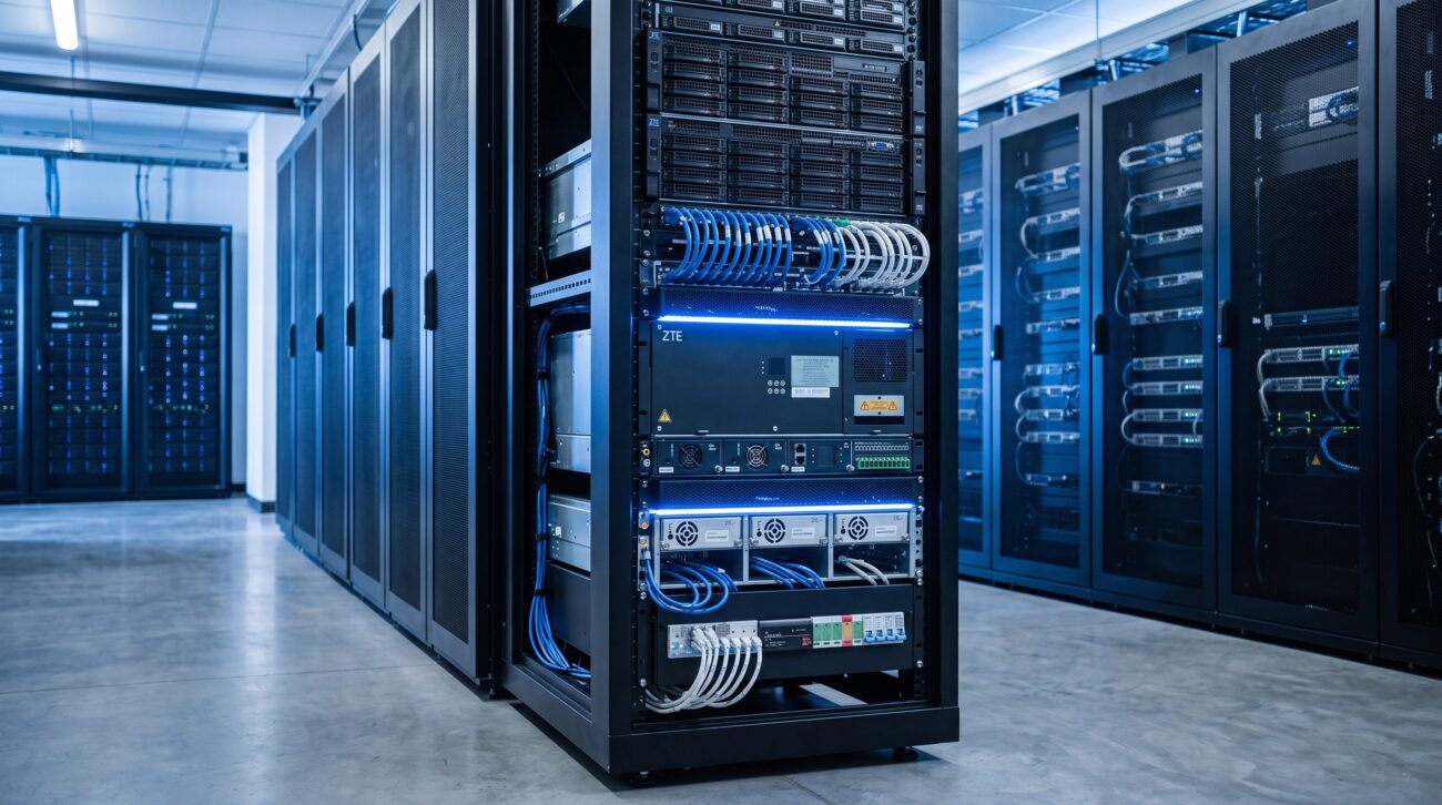
This document serves as the definitive systems engineering reference for the ZTE Power Subrack Installation Drawings suite. As a foundational element of ZTE’s carrier-grade power distribution infrastructure, these engineering drawings provide the precise mechanical, electrical, and thermal specifications required for the seamless integration of ZTE power subrack systems into existing and greenfield telecommunications installations. This technical datasheet covers the complete drawing portfolio, including dimensional layouts, cable routing schematics, grounding topologies, and equipment mounting templates.
SYSTEM HARDWARE TOPOLOGY
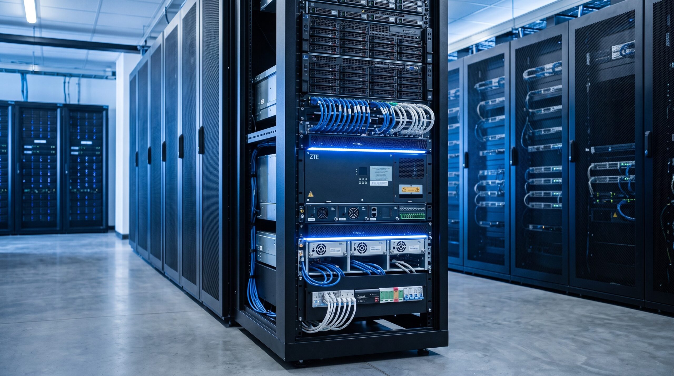
The ZTE Power Subrack Installation Drawings define a comprehensive architectural framework that encompasses the physical and logical interconnection of power distribution units (PDUs), rectifier modules, and battery backup systems. The drawing set includes:
– MECHANICAL DIMENSIONING LAYOUTS: Precise 2D and 3D isometric projections with full millimeter-grade tolerances for rack mounting (ETSI and 19-inch standards).
– CABLE ROUTING AND BUDGET SCHEMATICS: Color-coded harness diagrams indicating AC/DC power feed paths, bonding conductors, and signal cable segregation with minimum bend radius callouts.
– GROUNDING AND BONDING ARCHITECTURE: Detailed single-point ground reference designs, equipotential bonding connections, and surge protection device placement per Telcordia GR-1089-CORE.
– THERMAL MANAGEMENT GUIDELINES: Airflow direction indicators, clearance requirements for forced-air convection, and heat dissipation mapping for 1RU and 2RU subrack variants.
– FRONT AND REAR PANEL PORTRAITS: Exact cutout templates for LED indicators, circuit breaker toggles, and DC output terminal block access.
The drawing suite adheres to the ZTE Unified Power Architecture (UPA) standard, ensuring interoperability across ZTE’s entire portfolio of wireless, optical, and core routing equipment. Each drawing is revision-controlled and utilizes a layered AutoCAD format (DWG) alongside high-fidelity PDF outputs for field engineering use.
DATA & CONTROL PLANE CAPABILITIES
While primarily a physical installation resource, the ZTE Power Subrack Installation Drawings embed critical control plane signaling pathways for intelligent power management:
– MONITORING INTERFACE SPECIFICATIONS: Pinout definitions for RS-485 and CAN bus connections to the Subrack Management Controller (SMC), enabling real-time voltage, current, and temperature telemetry.
– ALARM RELAY WIRING SCHEMATICS: Normally-open/normally-closed contact assignments for major and minor alarm outputs to external building management systems (BMS) or network operation centers (NOC).
– FIRMWARE UPGRADE PATHWAY DIAGRAMS: Dedicated console and Ethernet management port locations with recommended IP addressing schemes for out-of-band management.
COMPONENT BREAKDOWN
The drawing set is organized into modular sub-documents that map directly to the physical bill of materials (BOM) for the ZTE Power Subrack:
– SUBRACK CHASSIS FRAME (E.g., ZXPWR-SR-2000 SERIES): Main structural drawings include front/back rail spacing, card guide slots, and EMI gasket placement.
– RECTIFIER MODULE SLOTS (E.g., ZXRECT-48/3000W): Detailed insertion/extraction mechanical interfaces, including locking lever mechanisms and backplane connector pin alignment.
– DC DISTRIBUTION PANEL (E.g., ZXDB-48/200A): Busbar layout, circuit breaker mounting footprints, and load connection terminal torque specifications.
– MONITORING & CONTROL UNIT (MCU): LCD bezel dimensions and capacitive touch button position schematics.
– BACKPLANE ASSEMBLY: High-current copper trace routing (2 oz. minimum), signal integrity via placement, and connector keying orientation.
OPERATIONAL SPECS MATRIX
All drawings are certified to the following operational parameter ranges, which are explicitly annotated on the mechanical drawings via tables and callout notes:
– INPUT VOLTAGE RANGE: -40 VDC to -60 VDC nominal (rectifier AC input: 85-300 VAC).
– OUTPUT VOLTAGE: -48 VDC (adjustable -42 to -58 VDC via software).
– MAXIMUM OUTPUT CURRENT: Up to 600A per subrack (depending on rectifier population).
– OPERATING TEMPERATURE RANGE: -5°C to +55°C (derated above 45°C).
– STORAGE TEMPERATURE RANGE: -40°C to +70°C.
– RELATIVE HUMIDITY: 5% to 95% (non-condensing).
– ALTITUDE: Up to 4,000 meters above sea level.
– MTBF: > 500,000 hours (per Telcordia SR-332, Issue 4).
| Parameter | Specification |
|---|---|
| Form Factor | 1RU / 2RU Chassis (Standard ETSI & 19-inch) |
| Switching Capacity | Up to 600A DC output current capacity |
| Power Supply | 1+1 Redundant AC/DC (85-300 VAC input) |
| Input Voltage Range | -40 VDC to -60 VDC nominal |
| Operating Temperature | -5°C to +55°C |
| MTBF | > 500,000 hours (Telcordia SR-332) |
REGULATORY COMPLIANCE
The ZTE Power Subrack Installation Drawings explicitly reference and satisfy the following regulatory and industry compliance frameworks:
– EMC: EN 55032 (Class A), EN 55024, FCC Part 15 Subpart B (Class A).
– SAFETY: EN 60950-1 / IEC 62368-1, UL 60950-1.
– ENVIRONMENTAL: RoHS 2 (2011/65/EU), WEEE (2012/19/EU), REACH.
– TELECOMMUNICATIONS: NEBS GR-63-CORE (Level 3), GR-1089-CORE (Level 3).
– ELECTRICAL: IEEE 487 (DC power systems for telecommunications).
All drawing notes and specifications are traceable to the latest revision of these standards, ensuring that installations completed using this drawing suite will meet carrier audit requirements.
📥 Download Technical Specification
Click the button below to view or download the full official PDF datasheet.

Leave a comment