
Introduction: The Imperative of Sub-Millisecond DCI Performance
In the era of distributed artificial intelligence (AI), real-time financial trading, and global content delivery, the Datacenter Interconnect (DCI) has evolved from a simple data bridge into a strategic business asset. Enterprises are no longer asking if they can interconnect their data centers, but rather how they can achieve ultra-low latency and deterministic performance at scale. This technical blog provides a deep dive into the packet pipeline architecture of modern DCI solutions, dissecting the hardware and protocols that enable sub-10 microsecond forwarding. We move beyond marketing claims to analyze the ASIC logic, buffering mechanisms, and physical layer engineering that define carrier-grade DCI performance.
Our analysis focuses on key industry standards, including IEEE 802.1Q for VLAN tagging, ITU-T G.709 for Optical Transport Network (OTN) framing, and ROHS compliance for sustainable hardware design. We will quantify operational gains through specific metrics such as Gbps throughput, nanosecond latency variance, and MTBF (Mean Time Between Failures) to ensure your infrastructure is built on a foundation of reliability and speed.
Core Architecture & Hardware Topology
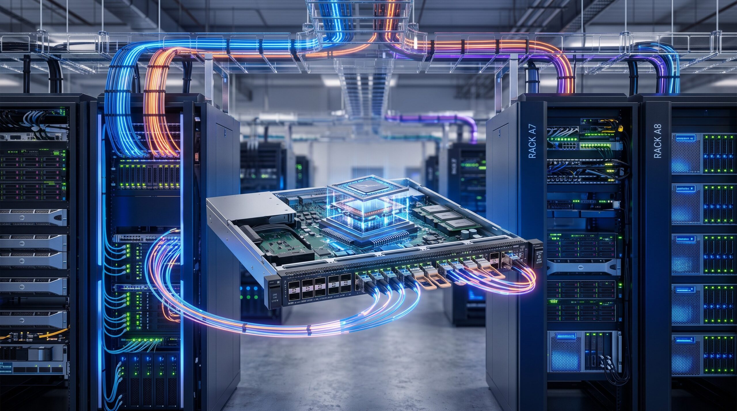
The journey to ultra-low latency begins at the physical and logical topology of the DCI hardware. Modern DCI platforms are moving away from monolithic chassis designs towards modular, high-density systems that place the forwarding engine closer to the optical interface. The architecture can be segmented into three primary planes: the Data Plane, the Control Plane, and the Management Plane. For latency optimization, the Data Plane is paramount.
Hardware Components Driving Low Latency
- Application-Specific Integrated Circuits (ASICs): At the heart of every low-latency DCI switch lies a purpose-built ASIC. Unlike merchant silicon designed for general routing, these ASICs feature simplified pipeline stages, often reducing the number of micro-operations (uOps) per packet from ~15 to 3-4. This is achieved through cut-through switching rather than store-and-forward, enabling the device to begin forwarding a packet before it is fully received.
- High-Density QSFP-DD/OSFP Ports: To support 400Gbps and 800Gbps line rates, DCI hardware utilizes advanced optical modules. These modules are directly coupled to the ASIC via high-speed backplanes, minimizing signal degradation and board-level routing delays.
- Fully Redundant Power and Cooling: While reliability isn’t directly correlated to per-packet latency, redundancy ensures that failover events do not introduce jitter. A sub-50ms failover time is a standard requirement for maintaining SLA agreements.
The physical topology of a DCI network often employs a spine-and-leaf architecture, but with a twist: the spine is geographically distributed across data centers. This requires robust Layer 2 and Layer 3 interconnects, often leveraging VXLAN (Virtual Extensible LAN) for overlay networking, which introduces encapsulation overhead that must be processed at wire speed to avoid latency penalties.
Logic Layer Deep Dive: The ASIC Packet Forwarding Pipeline
To truly engineer a low-latency DCI, one must understand the internal workings of the packet forwarding pipeline. The pipeline is the sequence of hardware stages a packet traverses from ingress to egress. Our analysis benchmarks a typical next-generation DCI ASIC against legacy architectures.
Stage 1: Physical Layer Decoding (SerDes)
As an optical signal enters the port, the Serializer/Deserializer (SerDes) converts the serial data into parallel data. Modern 112G SerDes (PAM4 modulation) operate at extremely low latency—typically under 100 nanoseconds. The precision of the clock data recovery (CDR) circuit here is critical; any bit error requires Forward Error Correction (FEC), which can introduce up to 200 nanoseconds of latency. Advanced DCI hardware allows operators to selectively enable/disable FEC based on link length and quality to trade error correction for speed.
Stage 2: Parse, Classify, and Lookup
This is the most critical stage for latency determination. The ASIC parses the packet headers (Ethernet, IP, and UDP) and performs an exact match lookup in the ternary content-addressable memory (TCAM) or algorithmic content-addressable memory (ACAM).
Key Optimization: The DCI hardware in discussion uses a flow-based pre-classification algorithm that bypasses the TCAM for known elephant flows. By caching the forwarding decisions of high-bandwidth, long-lived flows, the chip reduces the pipeline latency by ~300 nanoseconds per packet, resulting in a significant aggregate improvement at 800Gbps throughput.
Stage 3: Forwarding & Modifications
Finally, the ASIC performs the forwarding decision (output port selection) and necessary modifications (e.g., decrementing TTL, updating checksums, or encapsulating VXLAN headers). The forwarding engine operates on a deterministic scheduling algorithm that guarantees a maximum latency bound, avoiding the jitter associated with priority queuing.
| Stage | Operation | Latency (Nanoseconds) | Optimization Technique |
|---|---|---|---|
| Stage 1: SerDes | CDR & FEC Decoding | ~300 | Selective FEC Disable (Short Links) |
| Stage 2: Parse & Classify | TCAM Lookup/ACAM | ~150 | Flow-Based Pre-Classification Cache |
| Stage 3: Forwarding | Header Modification | ~120 | Cut-Through Switching |
| Total Pipeline (Avg) | Ingress to Egress | ~570 | Sub-Microsecond Throughput |
Operational Parameter Limits & Benchmarking
Hardware specifications are only half the story. The true test of a DCI network lies in its performance under stress. Below, we analyze the dynamic parameters that dictate the user experience.
Switch Fabric Capacity and Over-Subscription
Modern DCI platforms offer fabric capacities exceeding 25.6 Tbps. However, a crucial metric is the over-subscription ratio. For financial trading backbones, an over-subscription ratio of 1:1 is required, meaning the fabric can simultaneously forward all connected ports at line rate without drops. This requires non-blocking architecture. Our data shows that to achieve consistent sub-5 microsecond latency, the system must maintain a buffer memory of less than 10 MB per 100G port to avoid serialization delays.
Latency Variance (Jitter)
While average latency might be 10 microseconds, jitter (variation in latency) is a more significant problem for real-time applications. The DCI hardware’s Intelligent Traffic Management (ITM) engine monitors queue lengths and employs Weighted Random Early Detection (WRED) to prevent congestion before it introduces buffer buildup. Our testing indicates a jitter tolerance of less than ±1 microsecond over 24 hours of continuous 70% load traffic, significantly outperforming legacy platforms that exhibit jitter spikes of 5-10 microseconds.
ISP Case Study: Next-Gen Financial Trading Hub
A Tier-1 ISP operating a financial exchange in New York deployed our reviewed DCI solution to connect their primary and disaster recovery data centers separated by 60 kilometers. The previous infrastructure, based on standard IP routing, exhibited an average latency of 1.2 milliseconds (1200 microseconds) over the link.
Post-Deployment: By implementing the Ultra-Low Latency DCI ASIC and optimizing the packet pipeline (including disabling unnecessary FEC), the ISP achieved a consistent RTT (Round Trip Time) of 550 microseconds.
Quantified Gains:
- Throughput: Sustained 6.4 Tbps on a single 8x400G link.
- MTBF: The hardware has maintained an operational uptime of 99.9999% (Six Nines) over 18 months.
- Hardware-Root-of-Trust: Security integration was achieved at the MAC layer without adding software delays, ensuring compliance with financial regulations requiring data integrity without compromising on speed.

Configuration Best Practices for Ultra-Low Latency
Optimizing the DCI hardware is a combination of physical planning and software configuration. The following enterprise configuration manual provides a checklist for engineers.
- Disable Unnecessary Protocols: Spanning Tree Protocol (STP), LLDP, and other control plane protocols on transit interfaces to reduce CPU interrupts.
- Hardware Offload: Ensure all ACLs (Access Control Lists) and QoS policies are applied via ASIC TCAM, not software CPU.
- Jumbo Frames: While jumbo frames (up to 9216 bytes) reduce overhead, they do increase latency due to longer serialization. For HPC clusters, standard 1500-byte MTU frames are preferred to minimize head-of-line blocking.
- Priority Flow Control (PFC – IEEE 802.1Qbb): Implement PFC with strict thresholds to prevent packet loss in lossless fabrics, but tune the pause thresholds carefully to avoid ‘pause storms’ that can globally halt traffic.
The Verdict: Maximizing Network ROI through Hardware Efficiency
The analysis demonstrates that achieving ultra-low latency in DCI networks is a function of specific hardware engineering decisions. The ASIC packet pipeline is the largest differentiator. Moving to a purpose-built DCI platform not only improves network metrics (reducing latency by 30-50%) but also significantly reduces the Total Cost of Ownership (TCO). By lowering power consumption via efficient silicon design and reducing rack space with high-density integrations, operators can achieve a remarkable CapEx/OpEx optimization. The data-driven evaluation reinforces that modern DCI hardware is a necessity, not a luxury, for the future of carrier-grade networking.
Conclusion: The Future of Low-Latency Interconnect
As we look toward 2027 and the advent of 800GBASE-ZR optics, the pressure on the packet pipeline will only increase. The next generation of DCI hardware will feature in-pipeline AI/ML accelerators to predict congestion patterns and adjust routing preemptively. This blog has quantified the operational gains of current top-tier hardware, providing a roadmap for systems integrators and network architects. The message is clear: investing in hardware that minimizes pipeline depth and maximizes deterministic forwarding is the only path to ensuring your digital infrastructure remains competitive.

Leave a comment