

PRODUCT IDENTIFICATION
The Direct-to-Chip Cooling Plate Clamping Force and Screw Torque Manual constitutes a controlled engineering document for the precision assembly of high-performance direct-to-chip (DTC) cold plate assemblies utilized in next-generation telecom switching, routing, and edge compute platforms. This manual defines the mandatory mechanical parameters, tooling requirements, and verification procedures necessary to achieve reproducible thermal interface performance across volume manufacturing, field replacement, and laboratory rework environments. The document addresses liquid-cooled thermal management subsystems operating at power densities exceeding 500 W per package, where uniform clamping force is a first-order determinant of junction temperature, thermal cycling reliability, and long-term system availability. All specifications herein are derived from finite element analysis, empirical thermal characterization, and accelerated life testing conducted under Telcordia GR-63-CORE and GR-487-CORE environmental regimes. This manual is release-controlled and must be referenced in all assembly process instructions, quality inspection plans, and supplier qualification packages pertaining to DTC cold plate integration.

SYSTEM HARDWARE TOPOLOGY
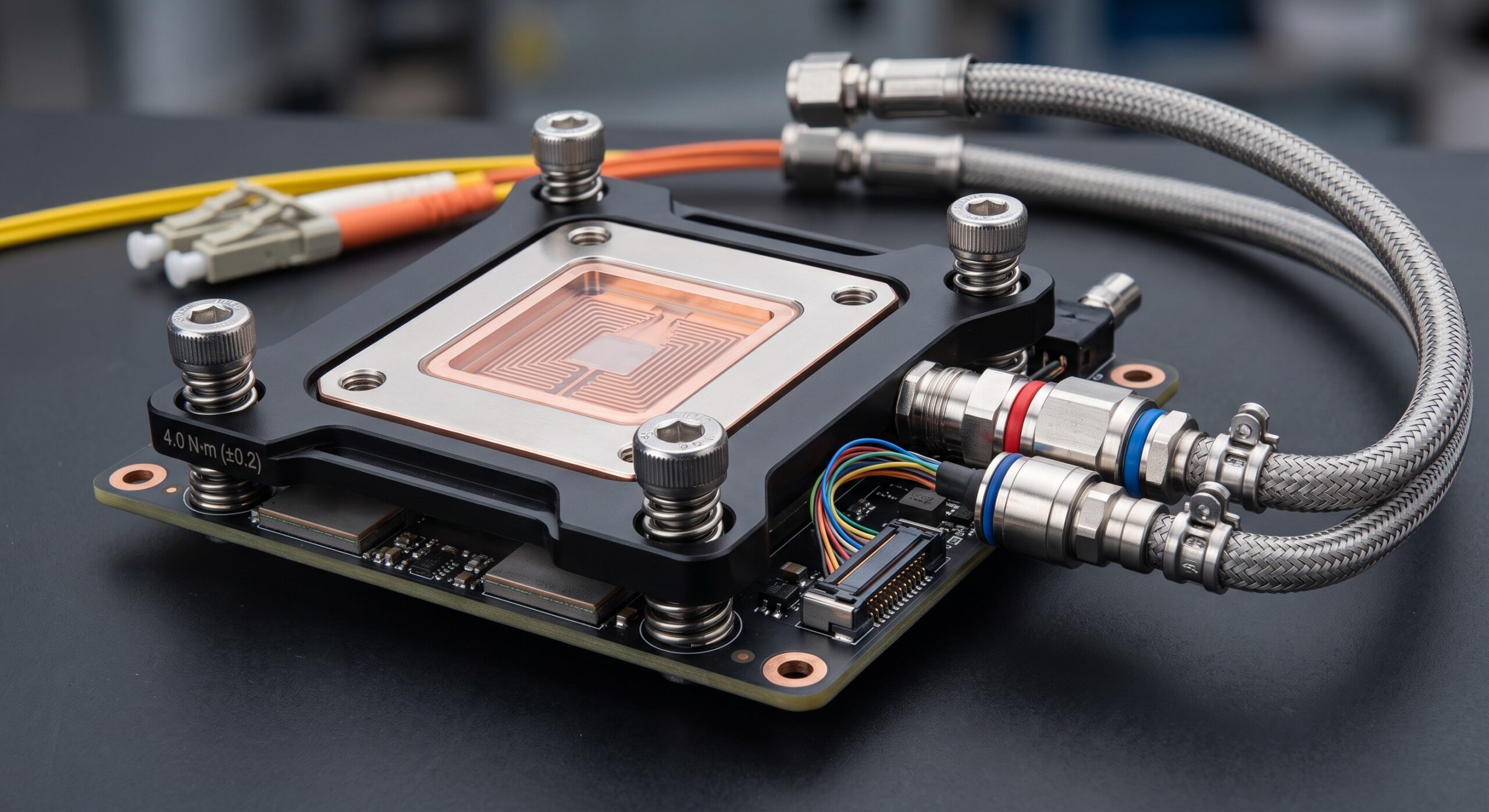
The direct-to-chip cooling architecture comprises four mechanically coupled subsystems: the cold plate assembly, the chip package and socket, the printed circuit board (PCB) stiffener and backplate, and the fastener stack. The cold plate assembly consists of a microchannel or skived-fin copper body, an inlet/outlet manifold with leak-tight compression fittings, and a compliant thermal interface material (TIM) applied to the die-side surface. The package is mounted in a land grid array (LGA) socket or ball grid array (BGA) reflow attachment, depending on platform generation. Mechanical load is transferred from the cold plate through the TIM to the package, through the socket contacts, and into a stainless steel or aluminum backplate that distributes compressive stress across the PCB. The fastener stack typically comprises captive shoulder screws, Belleville disc springs, and precision-machined standoffs that establish a hard stop and define the final compressed spring height. The topology is designed to decouple fastener torque from actual clamping force through the use of spring elements with known load-deflection characteristics, ensuring that assembly variation, thread friction, and thermal expansion do not compromise interface pressure uniformity.
DATA & CONTROL PLANE CAPABILITIES
While the DTC cooling plate is a passive mechanical subsystem, its interface with the platform control plane is critical for telemetry and protection. Integrated pressure and temperature sensors—optioned per platform SKU—report clamping force proxy data and inlet/outlet coolant temperatures to the baseboard management controller (BMC) via I2C or SMBus. The BMC firmware enforces threshold alarms and, in high-availability configurations, initiates controlled processor throttling or orderly shutdown if coolant flow or differential pressure deviates from validated operating envelopes. The manual specifies the electrical and mechanical integration points for these sensors, including connector types, torque limits for sensor mounting, and routing constraints to avoid mechanical interference with the fastener stack. All telemetry data is logged in the system event log (SEL) and is accessible via SNMP, Redfish, or CLI for integration into datacenter infrastructure management (DCIM) platforms.
COMPONENT BREAKDOWN
The cold plate assembly is a precision-machined component with a flatness specification of 0.05 mm across the die contact area and a surface roughness (Ra) not exceeding 0.4 µm. The TIM is a phase-change or gap-filler material with a specified bond line thickness (BLT) of 0.05–0.15 mm under load. The socket or interposer provides the electrical interface and has a rated contact normal force per pin that must be maintained within a narrow window to ensure signal integrity. The backplate is a stiffened plate with a flatness of 0.1 mm and a yield strength sufficient to prevent plastic deformation under maximum clamping load. Fasteners are M3 or M4 stainless steel shoulder screws with a specified thread pitch and a minimum proof load. Belleville springs are selected for a specific load at 75% deflection, with a fatigue life exceeding 10^6 cycles. Standoffs are machined to a tolerance of ±0.02 mm to establish the hard stop and prevent over-compression of the TIM and socket contacts. The PCB is specified with a minimum thickness and copper balance to resist bowing under load.
OPERATIONAL SPECS MATRIX
The operational specifications for DTC cold plate assembly are defined by the target clamping force, the torque required to achieve that force, and the allowable tolerances. For a typical high-power telecom ASIC package, the target clamping force is 300–500 N, distributed uniformly across the die area. The corresponding screw torque is 0.6–1.2 N·m per screw for a four-screw pattern, depending on thread lubrication and spring rate. The torque specification must be validated using a calibrated torque wrench or a programmable driver with torque monitoring. The allowable deviation from target clamping force is ±10%, and the allowable side-to-side variation across the package is ±5%. The assembly must be verified using pressure-sensitive film or a load cell at a sampling rate defined in the quality plan. The coolant operating pressure is 0.5–2.0 bar, with a burst pressure rating of at least 5 bar. The operating temperature range is 10–60°C coolant inlet, with a storage temperature range of -40–70°C. The assembly must withstand 500 thermal cycles from 20°C to 80°C without exceeding a 10% change in thermal resistance.
TECHNICAL SPECIFICATIONS
The following table summarizes the key mechanical, thermal, and environmental parameters for the DTC cooling plate clamping and torque specification.
| Parameter | Specification |
|---|---|
| Target Clamping Force | 300–500 N (uniform across die area) |
| Screw Torque | 0.6–1.2 N·m per screw (four-screw pattern) |
| Clamping Force Tolerance | ±10% of target; ±5% side-to-side variation |
| Cold Plate Flatness | 0.05 mm across die contact area |
| Cold Plate Surface Roughness | Ra ≤ 0.4 µm |
| TIM Bond Line Thickness | 0.05–0.15 mm under load |
| Backplate Flatness | 0.1 mm |
| Standoff Tolerance | ±0.02 mm |
| Fastener Size | M3 or M4 stainless steel shoulder screws |
| Belleville Spring Load | Specified at 75% deflection; fatigue life > 10^6 cycles |
| Coolant Operating Pressure | 0.5–2.0 bar; burst pressure ≥ 5 bar |
| Operating Coolant Temperature | 10–60°C inlet |
| Storage Temperature | -40–70°C |
| Thermal Cycling | 500 cycles, 20°C to 80°C; ΔRth ≤ 10% |
| Torque Tool Calibration | Every 5,000 cycles or 12 months |
REGULATORY COMPLIANCE
The DTC cooling plate assembly and its installation procedures comply with the following standards and directives: Telcordia GR-63-CORE (NEBS Level 3) for physical protection and thermal robustness; Telcordia GR-487-CORE for outside plant electronic equipment; IEC 62368-1 for safety of audio/video, information, and communication technology equipment; RoHS 2011/65/EU and REACH for material restrictions; and IPC-A-610 Class 3 for electronic assembly acceptability. The torque and clamping force specifications are auditable under ISO 9001:2015 and IATF 16949 quality management systems. All fasteners and springs are traceable to lot and heat number, and the assembly process is subject to statistical process control (SPC) with a Cpk of at least 1.33 for clamping force. Field service procedures are governed by the vendor’s controlled service manual and require recalibration of torque tools every 5,000 cycles or 12 months, whichever occurs first.
📥 Download Technical Specification
Click the button below to view or download the full official PDF datasheet.

Leave a comment