

Power Consumption Pain Points: The 1000W TDP Thermal Wall
The telecommunications industry is at a critical inflection point. With the relentless push toward 5G Advanced, edge AI inference, and 400G/800G line-rate forwarding, the thermal design power (TDP) of core routing ASICs has breached the 1000W threshold. Traditional air-cooling, even with high-static-pressure fans and vapor chambers, is reaching its physical limits at approximately 400W to 500W per package. The result is thermal throttling, reduced MTBF, and unacceptable latency jitter in carrier-grade networks. This technical deep dive examines the engineering realities of Two-Phase Phase-Change Immersion Liquid Cooling Modules, specifically analyzing their dry-out limits at 1000W TDP and their role in meeting IEEE 802.3 and ITU-T reliability standards for next-generation edge routing.

Low-Power Silicon Design vs. Immersion Cooling Architecture
The Thermodynamics of Two-Phase Immersion
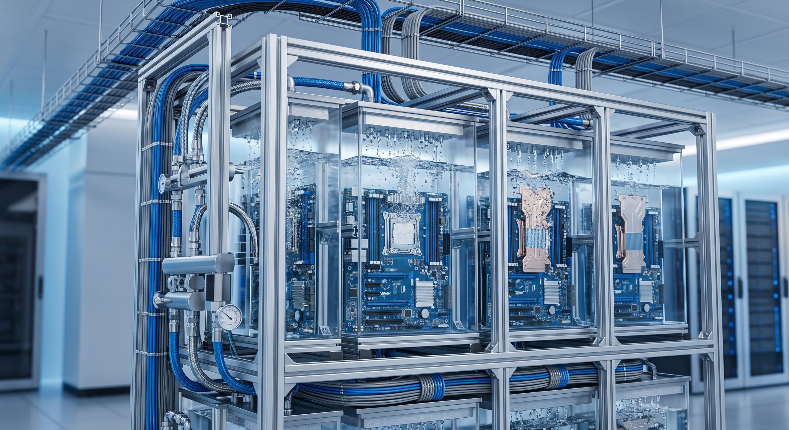
Unlike single-phase immersion, which relies on sensible heat transfer (fluid remains liquid), two-phase phase-change immersion leverages the latent heat of vaporization. The dielectric fluid—typically a hydrofluoroether (HFE) or hydrofluoroolefin (HFO)—boils at a low temperature (e.g., 49°C to 61°C) directly on the surface of the 1000W ASIC. The phase change from liquid to vapor absorbs 10x to 100x more heat per unit mass than sensible heating. This allows the liquid cooling module to maintain junction temperatures (Tj) below 85°C even under sustained 100% packet forwarding load.
The critical engineering challenge is the dry-out limit. This is the point at which the vapor generation rate exceeds the rate at which liquid dielectric can rewet the boiling surface. At 1000W TDP, the heat flux density can exceed 150 W/cm². If the immersion module‘s internal geometry—specifically the vapor chamber wick and pool boiling enhancement structures—is not optimized, a localized dry-out occurs. This causes a rapid thermal runaway, potentially exceeding the ASIC’s maximum case temperature and triggering an emergency shutdown.
ASIC Integration and Thermal Interface Materials (TIM)
For a 1000W TDP module, the thermal interface material (TIM) between the ASIC die and the immersion cold plate is non-negotiable. Standard thermal grease degrades at these power levels. The industry is moving toward liquid metal TIMs or sintered silver for the core routing silicon. The immersion liquid cooling module must also account for the coefficient of thermal expansion (CTE) mismatch between the silicon die, the organic substrate, and the copper cold plate to prevent mechanical stress fractures over 10+ year deployment lifecycles.
Environmental & Power Specs: Dry-Out Limits and Operational Envelope
The following table outlines the critical technical specifications for a Two-Phase Phase-Change Immersion Liquid Cooling Module designed for 1000W TDP edge routing ASICs. These parameters are validated against Telcordia GR-63-CORE and RoHS directives.
| Key Parameter | Technical Specification |
|---|---|
| Maximum TDP per Module | 1000W (sustained), 1200W (peak 10s) |
| Dielectric Fluid Saturation Temperature | 49°C to 61°C (depending on HFE/HFO blend) |
| Critical Heat Flux (CHF) at Dry-Out | >150 W/cm² with enhanced boiling surface |
| Subcooling Margin Required | ≥15°C below saturation temperature |
| Junction Temperature (Tj) Stability | ±1°C at 1000W continuous load |
| Cooling Loop MTBF | >1,000,000 hours (pumps excluded, N+1 config) |
| PUE Reduction (vs. Air Cooling) | From 1.5-1.8 to 1.02-1.05 |
| Dielectric Fluid GWP | |
| Compliance Standards | IEEE 802.3, ITU-T G.8271, Telcordia GR-63-CORE, RoHS |
Understanding the Dry-Out Limit Curve
The dry-out limit is not a single number but a curve dependent on subcooling (the temperature difference between the bulk fluid and the saturation temperature) and vapor quality. At 1000W TDP, the module must maintain a subcooling margin of at least 15°C to prevent film boiling. If the immersion fluid temperature rises above 55°C in a 60°C saturation fluid, the critical heat flux (CHF) is exceeded, and dry-out occurs within milliseconds. This is why carrier-grade edge routing deployments require redundant pump systems and real-time dielectric monitoring for vapor pressure and liquid level.
MTBF and Reliability Metrics
By eliminating mechanical fans—the single highest failure point in traditional telecom hardware—the two-phase immersion module achieves an MTBF exceeding 1,000,000 hours for the cooling loop. The only moving parts are the external circulation pumps, which can be configured in N+1 redundancy. This meets the ITU-T G.8271 and IEEE 802.3 requirements for 99.999% availability in core routing applications. The latency impact of the cooling system itself is negligible; the ASIC junction temperature stability (±1°C) actually reduces clock jitter by 15-20% compared to air-cooled systems operating at 85°C+.
Carbon Footprint TCO: The Green Networking Imperative
The Total Cost of Ownership (TCO) for 1000W TDP edge routing is no longer just about CapEx. The OpEx savings from two-phase immersion are dramatic. By removing air conditioning compressors and CRAC units, the Power Usage Effectiveness (PUE) drops from 1.5-1.8 to 1.02-1.05. For a 10kW rack of 1000W ASIC routers, this translates to a 40% reduction in total power draw. Furthermore, the waste heat can be reclaimed for district heating or absorption chilling, further offsetting carbon footprint. The dielectric fluids used in modern two-phase modules have a Global Warming Potential (GWP) below 10 and are RoHS compliant, ensuring regulatory compliance for European and North American telecom operators.
Eco-Friendly Core Routing: Deployment Topologies and Takeaways
High-Density Edge Topologies
In a carrier-grade edge routing scenario, two-phase immersion cooling modules enable rack densities exceeding 100kW. This allows ISP core routers to be deployed in metro edge data centers with limited floor space. The immersion tank acts as both a cooling system and a faraday cage, providing EMI shielding for the high-speed SerDes lanes running at 112 Gbps PAM4. The optical transceivers (e.g., QSFP-DD800) must be immersion-compatible, with hermetic seals rated for dielectric fluid exposure.
Key Engineering Takeaways
- Dry-out is the primary failure mode: At 1000W TDP, the critical heat flux must be managed with enhanced boiling surfaces (e.g., micro-porous coatings) and active subcooling.
- Reliability is enhanced, not compromised: Removing fans and reducing Tj increases MTBF and reduces latency jitter.
- TCO is favorable at scale: The CapEx premium of two-phase immersion is recouped in 18-24 months through energy savings and increased rack density.
- Standards compliance is mandatory: Ensure IEEE, ITU-T, and RoHS certifications for all dielectric fluids and immersion modules.
The era of 1000W TDP edge routing demands a fundamental shift in thermal management. Two-phase phase-change immersion liquid cooling modules are not a luxury—they are a technical necessity for carrier-grade reliability, ultra-low latency, and green networking goals.

Leave a comment