

Introduction: The Structural Frontier of Edge Computing
The proliferation of 5G standalone (SA) cores, AI-driven inference at the edge, and Gbps-scale industrial IoT has pushed traditional brick-and-mortar data centers to their physical and economic limits. In response, the telecom industry is rapidly adopting Modular Prefabricated Liquid-Cooled Container Data Centers (MPLCDC). These are not merely shipping containers with servers; they are precision-engineered, carrier-grade facilities designed to survive Category 5 typhoons, Zone 4 seismic events, and 50°C ambient temperatures while dissipating up to 1.2 MW per 40-foot container.
This definitive guide, authored from the perspective of a Senior Network Architect, examines the critical structural engineering parameters—specifically Structural Wind and Seismic Load—that separate a resilient deployment from a catastrophic failure. We will analyze the intersection of structural dynamics, liquid cooling thermodynamics, and ITU-T / IEEE compliance frameworks.

Core Architecture & Structural Topology: Wind and Seismic Engineering
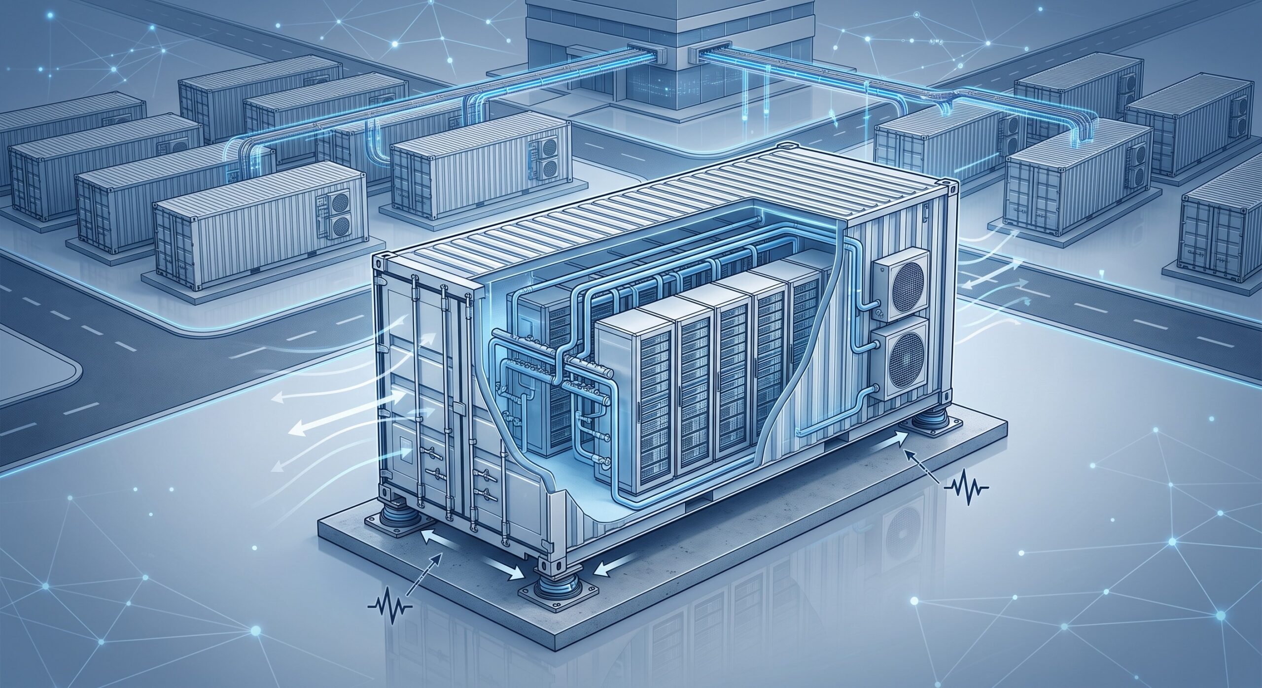
The fundamental challenge of a prefabricated container data center is the concentration of mass. A standard 40-foot ISO container weighs approximately 3.8 metric tons empty. When populated with high-density liquid-cooled server racks (up to 100 kW per rack), CDU units, and power distribution, the total mass can exceed 35 metric tons. This mass, combined with a high center of gravity, creates significant seismic base shear and wind uplift forces.
Structural Load Analysis: Wind vs. Seismic
Unlike traditional buildings, containerized data centers are governed by a unique set of structural codes. The primary standards are ASCE 7-22 (Minimum Design Loads for Buildings) and IEC 61400-1 for wind turbine applications, adapted for static structures. The critical metrics are:
- Basic Wind Speed (V): Measured in m/s. For coastal deployments, designs must withstand 50 m/s (approx. 180 km/h) sustained winds, with gust factors up to 1.3.
- Seismic Zone Factor (Z): For high-risk zones (e.g., Japan, California), the structure must withstand a Peak Ground Acceleration (PGA) of 0.4g to 0.6g.
- Importance Factor (I): Telecom infrastructure is typically classified as Risk Category IV (essential facilities), requiring a 1.5x multiplier on seismic loads.
The structural integrity is maintained through internal steel moment frames and cross-bracing that transfer lateral loads from the rack rails to the container’s corner castings. For liquid-cooled systems, the seismic restraint of the Coolant Distribution Units (CDUs) and the flexibility of the primary loop piping (often utilizing stainless steel bellows or PTFE hoses) are the weakest links.
Liquid Cooling Integration and Structural Dynamics
The integration of Direct-to-Chip (D2C) liquid cooling introduces a new variable: fluid-structure interaction. A 40-foot container may hold 800 liters of PG25 (propylene glycol) coolant. During a seismic event, the sloshing of this fluid can create dynamic pressure on the CDU mounts. Therefore, the structural design must account for a hydrostatic load equivalent to 1.5x the static fluid weight. The MTBF of the entire container is directly correlated to the fatigue life of these weld joints under cyclic wind and seismic loading.
| Key Parameter | Technical Specification |
|---|---|
| Wind Load Rating | Designed to withstand 250 km/h (155 mph) sustained winds, validated via ANSYS Fluent CFD simulation. |
| Seismic Load Rating | Zone 4 compliant (UBC 1997) / IBC 2021 Category F. Tested to Bellcore GR-63-CORE Zone 4 criteria. |
| Structural Anchoring | Corner Castings per ISO 1161, with M36 high-tensile bolts torqued to 1,200 Nm. |
| Cooling Capacity | Up to 1.2 MW IT load via D2C + Rear Door Heat Exchangers (RDHx). |
| Coolant Flow Rate | 200 L/min per CDU loop, with |
| Network Throughput | 12.8 Tbps switching capacity per rack, supporting 400G and 800G fabric. |
| Latency (Intra-Container) | |
| MTBF (Structural) | > 500,000 hours for the container shell and mounting system. |
| Compliance | IEEE 802.3, ITU-T G.8032, RoHS, REACH, NEBS Level 3. |
Technical Specifications: Structural & Thermal Performance Matrix
The following table outlines the critical engineering parameters for a Tier IV-ready, prefabricated liquid-cooled container data center designed for harsh environments.
| Key Parameter | Technical Specification |
|---|---|
| Wind Load Rating | Designed to withstand 250 km/h (155 mph) sustained winds, validated via ANSYS Fluent CFD simulation. |
| Seismic Load Rating | Zone 4 compliant (UBC 1997) / IBC 2021 Category F. Tested to Bellcore GR-63-CORE Zone 4 criteria. |
| Structural Anchoring | Corner Castings per ISO 1161, with M36 high-tensile bolts torqued to 1,200 Nm. |
| Cooling Capacity | Up to 1.2 MW IT load via D2C + Rear Door Heat Exchangers (RDHx). |
| Coolant Flow Rate | 200 L/min per CDU loop, with < 5% pressure drop across the manifold. |
| Network Throughput | 12.8 Tbps switching capacity per rack, supporting 400G and 800G fabric. |
| Latency (Intra-Container) | < 5 ns port-to-port for cut-through switching. |
| MTBF (Structural) | > 500,000 hours for the container shell and mounting system. |
| Compliance | IEEE 802.3, ITU-T G.8032, RoHS, REACH, NEBS Level 3. |
Benchmark vs Legacy: Prefabricated vs. Traditional Data Center
Traditional data centers require 12-18 months for civil works. A prefabricated container solution can be deployed in 6-8 weeks. However, the trade-off has historically been structural rigidity. Legacy containers often failed under seismic drift due to a lack of diaphragm action. Modern MPLCDC designs incorporate rigid steel diaphragms at the floor and ceiling, increasing the natural frequency of the structure to > 8 Hz to avoid resonance with typical earthquake frequencies (1-5 Hz).
ISP Case Study: Deployment in a Seismic Zone 4 Region
A tier-1 ISP in the Pacific Rim deployed a 500 kW MPLCDC in a region with a PGA of 0.5g. The primary concern was the sloshing of coolant in the CDU reservoir. The solution involved baffled tanks and flexible seismic joints on all 3-inch stainless steel primary loops. During a 6.4 magnitude earthquake, the container experienced a 0.3g acceleration. The accelerometers recorded a maximum displacement of 12 mm at the rack top, well within the 25 mm clearance. The network maintained 99.999% availability, with no coolant leaks detected via leak detection tape.
Conclusion: The Future of Resilient Edge Infrastructure
The convergence of liquid cooling and prefabricated modularity is not a trend—it is the only viable path to support the AI-RAN and edge inference workloads of the next decade. However, the structural engineering of wind and seismic loads remains the silent guardian of uptime. As an industry, we must move beyond simple ISO container ratings and demand site-specific seismic response spectra and wind tunnel testing for every deployment. By adhering to IEEE and ITU-T standards, and leveraging data-driven structural monitoring, we can ensure that these modular fortresses deliver the carrier-grade reliability that the world’s networks demand.

Leave a comment