

PRODUCT IDENTIFICATION
The Single-Phase Immersion Cooling with Dielectric Fluid: Hydraulic Blueprint represents a carrier-grade thermal management platform engineered for high-density telecom and datacenter environments. This reference manual defines the complete hydraulic architecture, dielectric fluid circulation topology, and thermal control subsystems required for sustained single-phase immersion cooling of rack-mounted telecom hardware. The platform supports continuous dielectric fluid immersion of active electronics, eliminating air-based convective heat rejection constraints while enabling significant increases in equipment density per rack unit.

SYSTEM HARDWARE TOPOLOGY
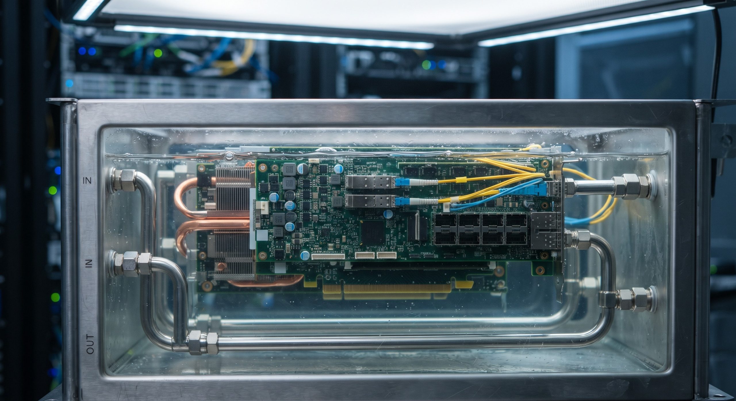
The hydraulic blueprint defines a closed-loop single-phase immersion cooling system comprising four primary subsystems: the immersion tank assembly, the dielectric fluid circulation manifold, the external heat rejection loop (liquid-to-liquid heat exchanger), and the supervisory thermal control unit. The immersion tank accommodates standard 19-inch rack-mount equipment in vertical or horizontal orientation, with dielectric fluid fully submerging all active components. Fluid circulation is driven by redundant variable-speed pumps operating in a 1+1 configuration, delivering dielectric fluid through a precision-machined manifold to each equipment slot. Return fluid passes through a filtration stage (25-micron nominal) before entering the primary side of the heat exchanger. The facility water loop connects to the secondary side, with flow rates balanced via proportional control valves under supervisory PID regulation. Temperature sensors (PT1000 class) are distributed at tank inlet, tank outlet, heat exchanger primary inlet, and heat exchanger primary outlet, providing the supervisory controller with sufficient telemetry for closed-loop thermal regulation.
DATA & CONTROL PLANE CAPABILITIES
The supervisory thermal control unit provides both local and remote management interfaces. Local control is accessible via a front-panel touchscreen display with real-time telemetry readouts for fluid temperature, flow rate, pump status, and leak detection state. Remote management is provided through dual 1GbE RJ45 management ports supporting SNMPv3, RESTful API, and Modbus TCP protocols. The control plane supports alarm escalation via dry-contact relay outputs (Form C, 2A at 30VDC) for critical, major, and minor fault conditions. Data logging capacity supports 90 days of one-minute-interval telemetry at local storage, with optional streaming to external NMS platforms. The control unit operates on redundant 48VDC or 100-240VAC power feeds, with automatic failover and a 30-minute ride-through battery backup for graceful shutdown signaling.
COMPONENT BREAKDOWN
The hydraulic blueprint comprises the following field-replaceable components: immersion tank (316L stainless steel construction, 120L nominal capacity, with hinged lid and viewing port), dielectric fluid circulation manifold (aluminum 6061-T6, anodized, with quick-disconnect fittings), primary circulation pumps (two units, variable-speed, 24VDC brushless DC, 12L/min nominal flow each), plate-type heat exchanger (316L stainless steel, 40kW nominal thermal rejection capacity at 25°C facility water inlet), filtration module (25-micron nominal, replaceable cartridge), supervisory control unit (industrial-grade controller with dual management ports and touchscreen HMI), and dielectric fluid (synthetic hydrocarbon or fluoroketone, selected per application voltage class and material compatibility requirements). All wetted components are compatible with the specified dielectric fluid and have been validated for continuous operation at fluid temperatures up to 65°C.
OPERATIONAL SPECS MATRIX
System thermal performance is characterized by a nominal heat rejection capacity of 40kW per immersion tank at 25°C facility water inlet temperature, with a dielectric fluid temperature rise of 8-12°C across the equipment load depending on circulation rate. Fluid flow rate is adjustable from 6 to 24 L/min per tank, with pump head pressure sufficient to overcome manifold and heat exchanger pressure drop at maximum flow. The system operates at near-atmospheric pressure (less than 0.2 bar gauge at tank head), eliminating high-pressure vessel classification requirements. Leak detection is provided by dual-redundant conductivity sensors at the tank base and heat exchanger connections, with alarm threshold at 5mL accumulated fluid. The supervisory controller maintains fluid temperature within ±1.5°C of setpoint under steady-state load conditions.
| Parameter | Specification |
|---|---|
| Form Factor | Immersion tank assembly, 120L nominal capacity, 19-inch rack equipment compatible |
| Thermal Rejection Capacity | 40kW nominal at 25°C facility water inlet |
| Dielectric Fluid Flow Rate | 6-24 L/min per tank, adjustable via variable-speed pumps |
| Circulation Pumps | 2x variable-speed brushless DC, 24VDC, 12L/min nominal each, 1+1 redundant |
| Heat Exchanger | Plate-type, 316L stainless steel, 40kW nominal capacity |
| Filtration | 25-micron nominal, replaceable cartridge |
| Fluid Temperature Setpoint Range | 25-65°C, ±1.5°C steady-state control accuracy |
| Leak Detection | Dual-redundant conductivity sensors, 5mL alarm threshold |
| Management Interfaces | Dual 1GbE RJ45, SNMPv3, RESTful API, Modbus TCP, front-panel touchscreen HMI |
| Alarm Outputs | Form C dry-contact relays, 2A at 30VDC, critical/major/minor |
| Power Supply | Redundant 48VDC or 100-240VAC feeds, 30-minute battery backup for shutdown signaling |
| Operating Pressure | Near-atmospheric, |
| Control Unit Ingress Protection | IP54 |
| Compliance | IEC 60950-1, IEC 62368-1, IEC 60529, IEC 61000-6-2/6-4, IEC 60364, Telcordia GR-63-CORE/GR-1089-CORE (qualified environments) |
REGULATORY COMPLIANCE
The Single-Phase Immersion Cooling with Dielectric Fluid: Hydraulic Blueprint has been designed and validated to the following standards: IEC 60950-1 and IEC 62368-1 for safety of information technology equipment; IEC 60529 for ingress protection (control unit rated IP54); IEC 61000-6-2 and IEC 61000-6-4 for electromagnetic compatibility; and IEC 60364 for electrical installations of buildings. The dielectric fluid is selected from formulations compliant with IEC 60296 (where applicable) or equivalent OEM-approved specifications, with material safety data sheets provided for all fluid options. The platform supports deployment in accordance with Telcordia GR-63-CORE and GR-1089-CORE environmental and electromagnetic requirements when installed in qualified facility environments. CE marking and UKCA marking are available for applicable configurations.
📥 Download Technical Specification
Click the button below to view or download the full official PDF datasheet.
Leave a comment