
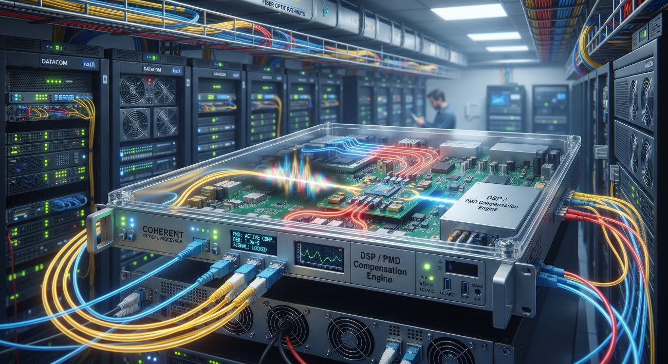
Ultra-Low Latency Demands in Coherent Optical Transport
In modern 400G/800G coherent optical transport networks, the tolerance to Polarization-Mode Dispersion (PMD) directly dictates the achievable reach and system margin. While legacy intensity-modulated direct-detection (IMDD) systems struggled with PMD-induced pulse broadening at 10G and 40G, today’s coherent receivers leverage high-speed DSP ASICs to perform adaptive equalization in the electrical domain. However, this digital compensation is not without cost. The packet pipeline latency introduced by the blind equalization algorithms—specifically the Constant Modulus Algorithm (CMA) and decision-directed least-mean-square (DD-LMS) filters—must be rigorously bounded to meet strict ITU-T G.709 and IEEE 802.3 latency budgets for 5G fronthaul and financial trading applications. This deep dive analyzes the internal ASIC packet pipeline required to mitigate Differential Group Delay (DGD) up to 100-150 ps while maintaining sub-microsecond forwarding latency .
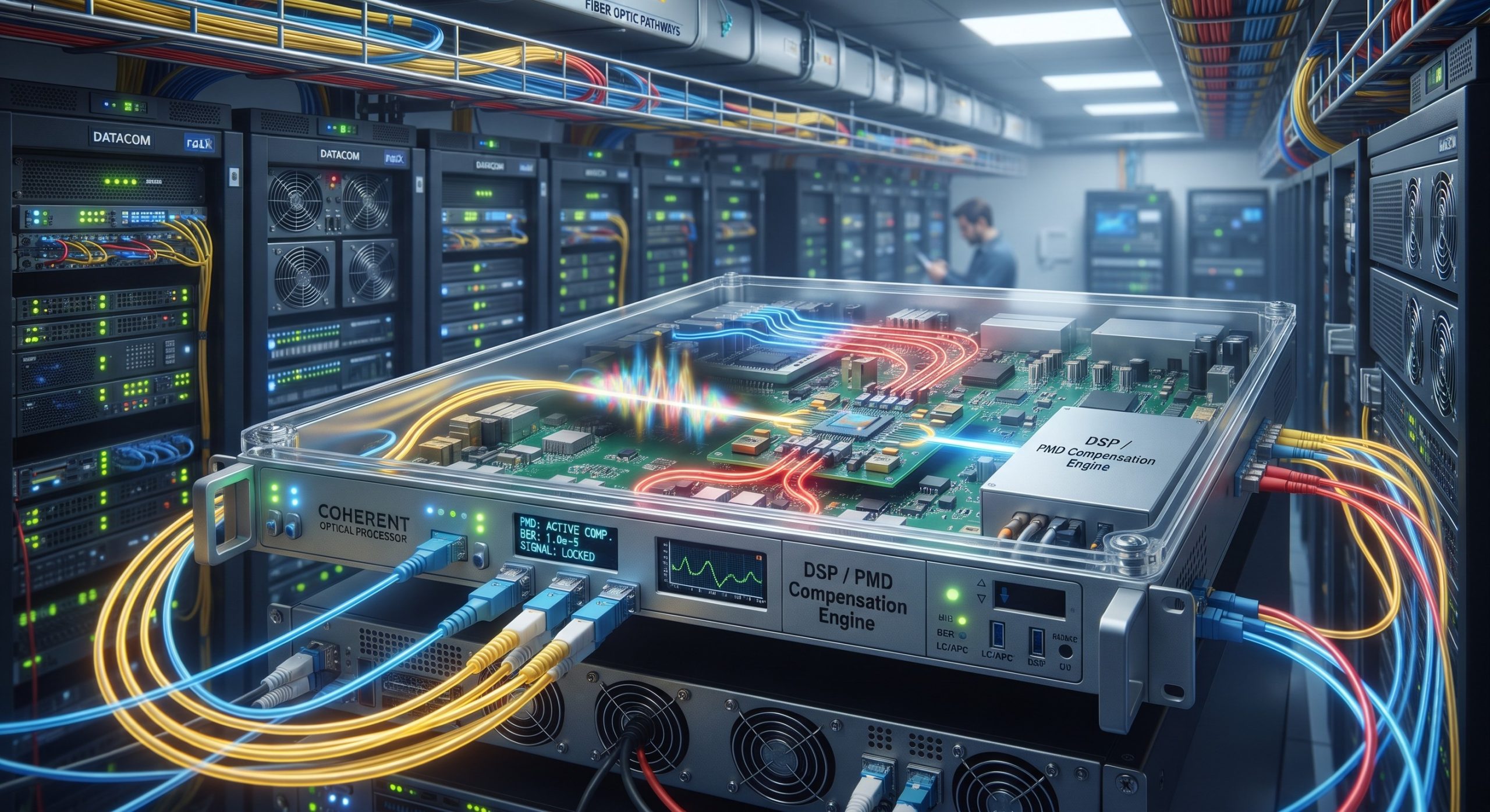
ASIC Packet Forwarding Pipeline: PMD Equalization Logic
Blind Adaptation and Tap-Length Constraints
The core of PMD compensation in a coherent receiver relies on a butterfly-structured adaptive FIR filter (often implementing a 2×2 MIMO equalizer). To track the time-varying Principal States of Polarization (PSP) caused by environmental vibrations and thermal fluctuations, the ASIC must continuously update the filter coefficients. The critical metric here is convergence time. A typical carrier-grade DSP utilizes a CMA for initial blind acquisition, which is robust against phase noise but sensitive to high DGD. Once the Bit Error Rate (BER) falls below the FEC threshold (e.g., 1E-2 for oFEC), the pipeline switches to DD-LMS for finer tracking. The packet pipeline delay in this stage is heavily dependent on the number of T/2-spaced taps; typical implementations for long-haul applications utilize 12–16 taps per butterfly branch to compensate for up to 150 ps of mean DGD, introducing a static latency of roughly 50–80 ns within the equalizer block alone .
Stokes Space Tracking vs. Time-Domain Equalization
To minimize the forwarding latency without sacrificing PMD tolerance, advanced ASIC architectures are migrating toward Stokes-space-based polarization demultiplexing. Unlike traditional time-domain butterfly filters that require long tap delays to emulate the inverse Jones matrix, Stokes-space tracking (often using Extended Kalman Filters) can separate the polarization states before equalization. This architectural shift reduces the required tap length for PMD compensation because the DGD is estimated and tracked as a rotation on the Poincaré sphere rather than a time-domain convolution. By decoupling polarization demultiplexing from PMD equalization, the packet pipeline can achieve a latency reduction of up to 30% compared to legacy CMA-only pipelines, while maintaining a DGD tolerance of 100 ps with a penalty of .
| Key Parameter | Technical Specification |
|---|---|
| DSP Process Node | 7nm CMOS |
| Symbol Rate / Baud Rate | 64 GBaud (nominal) |
| Equalizer Architecture | 2×2 MIMO Butterfly (T/2 spaced) |
| Tap Length (per branch) | 12 – 16 taps |
| Max Compensable Mean DGD | 100 – 150 ps |
| Equalizer Pipeline Latency | 50 – 80 ns (static) |
| Tracking Loop Latency (DD-LMS) | ~15 ns update cycle |
| FEC Overhead (oFEC) | ~15.3% (nominal) |
| Power Consumption (DSP only) | ~45 W (typical) |
Performance Metrics Matrix: Latency vs. PMD Tolerance
The following table quantifies the trade-offs between digital equalization depth, power consumption, and PMD compensation range for a representative 7nm coherent DSP operating at 64 GBaud.
| Key Parameter | Technical Specification |
|---|---|
| DSP Process Node | 7nm CMOS |
| Symbol Rate / Baud Rate | 64 GBaud (nominal) |
| Equalizer Architecture | 2×2 MIMO Butterfly (T/2 spaced) |
| Tap Length (per branch) | 12 – 16 taps |
| Max Compensable Mean DGD | 100 – 150 ps |
| Equalizer Pipeline Latency | 50 – 80 ns (static) |
| Tracking Loop Latency (DD-LMS) | ~15 ns update cycle |
| FEC Overhead (oFEC) | ~15.3% (nominal) |
| Power Consumption (DSP only) | ~45 W (typical) |
Traffic Shaping and Low-Latency Topologies
FEC Interleaving Impact on Jitter
While the ASIC equalizer handles the physical layer PMD, the interaction with Forward Error Correction (FEC) introduces additional latency jitter. High-gain oFEC (Open FEC) or CFEC utilizes block interleaving to spread burst errors caused by residual uncorrected DGD. This interleaving depth directly adds to the end-to-end latency. For ultra-low latency applications (e.g., per hop), operators must configure the DSP to use a reduced interleaver depth or bypass the high-gain FEC in favor of lower-latency HD-FEC (Hard-Decision FEC), accepting a reduced PMD margin (typically capping DGD tolerance at ~40 ps) to prioritize packet pipeline throughput .
Deployment in Low-Latency Topologies
In metro DCI (Data Center Interconnect) topologies where latency is mandatory, the coherent receiver must be configured with a fixed equalizer after initial link commissioning if the fiber plant is stable (low environmental variation). By freezing the DD-LMS taps after the initial CMA convergence, the DSP eliminates the tracking loop latency associated with continuous coefficient updates. This configuration is viable only when the PMD_Q of the deployed fiber is well below the 0.20 ps/√km ITU-T recommendation and the DGD is statistically stable (Maxwell distribution variance is low), ensuring that the static equalizer remains optimized for the Principal States of Polarization over the system’s MTBF interval .
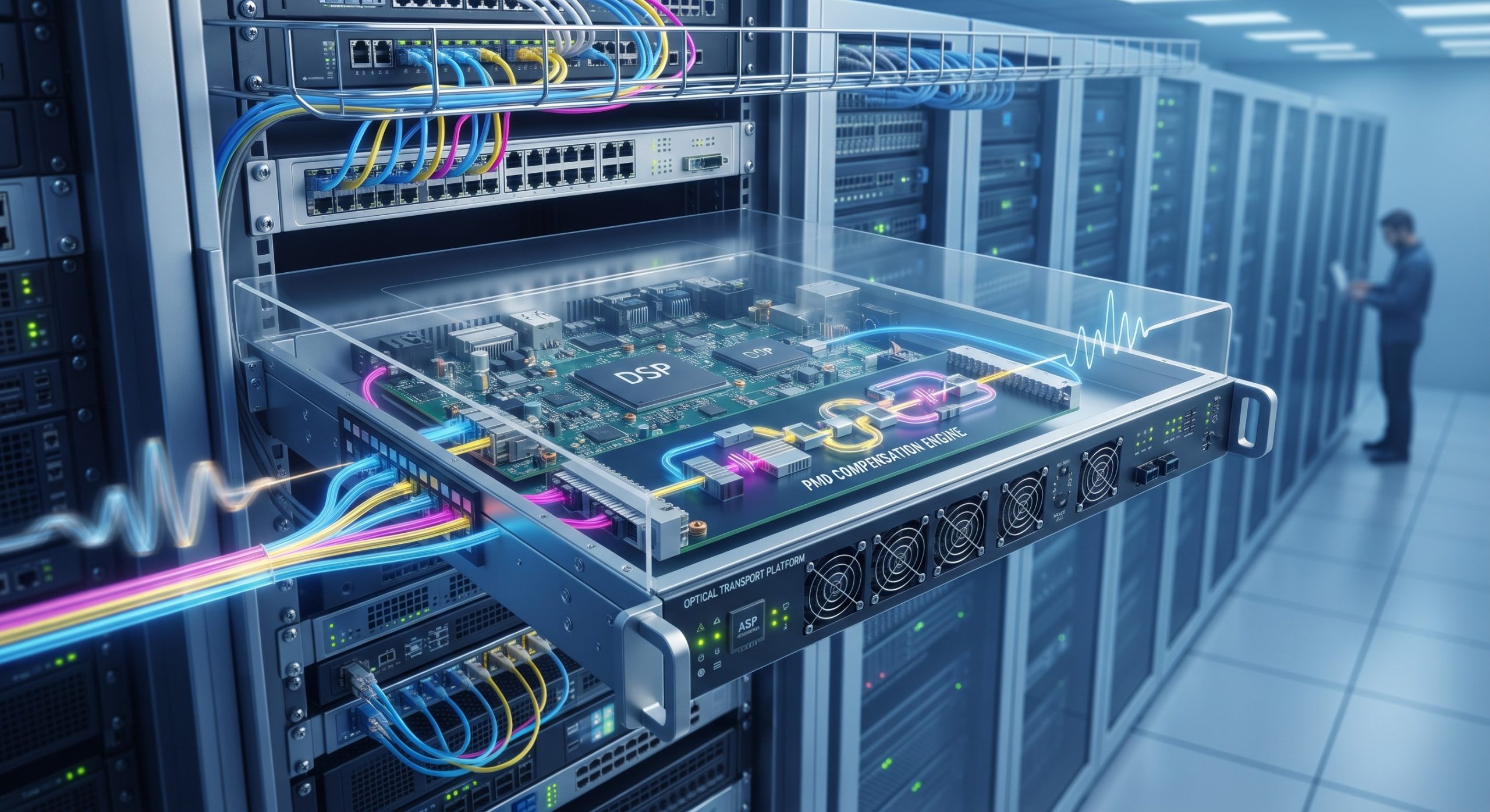
Verdict: Balancing PMD Resilience and Latency
The engineering of PMD compensation in coherent receivers is a delicate optimization between DGD tolerance and packet pipeline latency. While modern ASIC DSPs can theoretically compensate for DGD exceeding 150 ps, doing so via long tap-length time-domain equalizers imposes a latency penalty that is increasingly unacceptable for time-sensitive networks (TSN) and 5G fronthaul. The industry trajectory is clear: moving toward frequency-domain equalization (FDE) and Stokes-space tracking to decouple PMD mitigation from tap-delay, thereby achieving sub-100 ns equalizer latency while maintaining compliance with ITU-T G.691 and IEEE 802.3 optical interface standards. For network architects, the key takeaway is to validate the DSP latency profile under worst-case DGD conditions (e.g., 99.99% probability) rather than relying solely on static datasheet specifications .
Leave a comment