
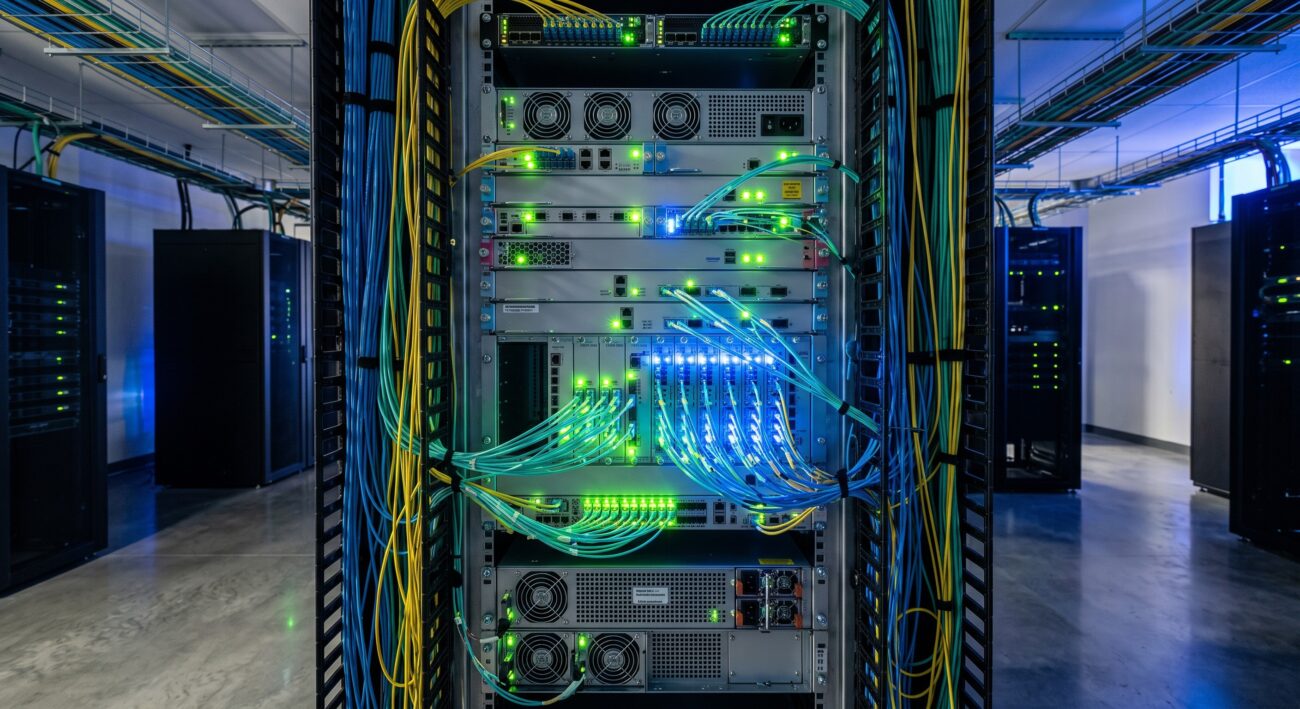
Introduction: The Unlit Potential of Dark Fiber
In an era where enterprise data demands are doubling every few years, dark fiber represents a strategic asset for organizations seeking ultimate control over their network destiny. However, merely leasing a strand of unlit fiber is only the first step. The process of lighting dark fiber—selecting the right optical hardware to activate this passive infrastructure—determines whether a network achieves carrier-grade reliability or becomes a liability.
Dark fiber refers to unused optical fiber that has been installed but lacks the active optical transmission equipment to carry signals . For enterprises, dark fiber solutions offer unlimited bandwidth potential, with network capacity constrained only by the chosen optics and transceivers . This guide provides a technical deep-dive into the hardware ecosystem required to transform dark fiber into a robust, mission-critical backbone.
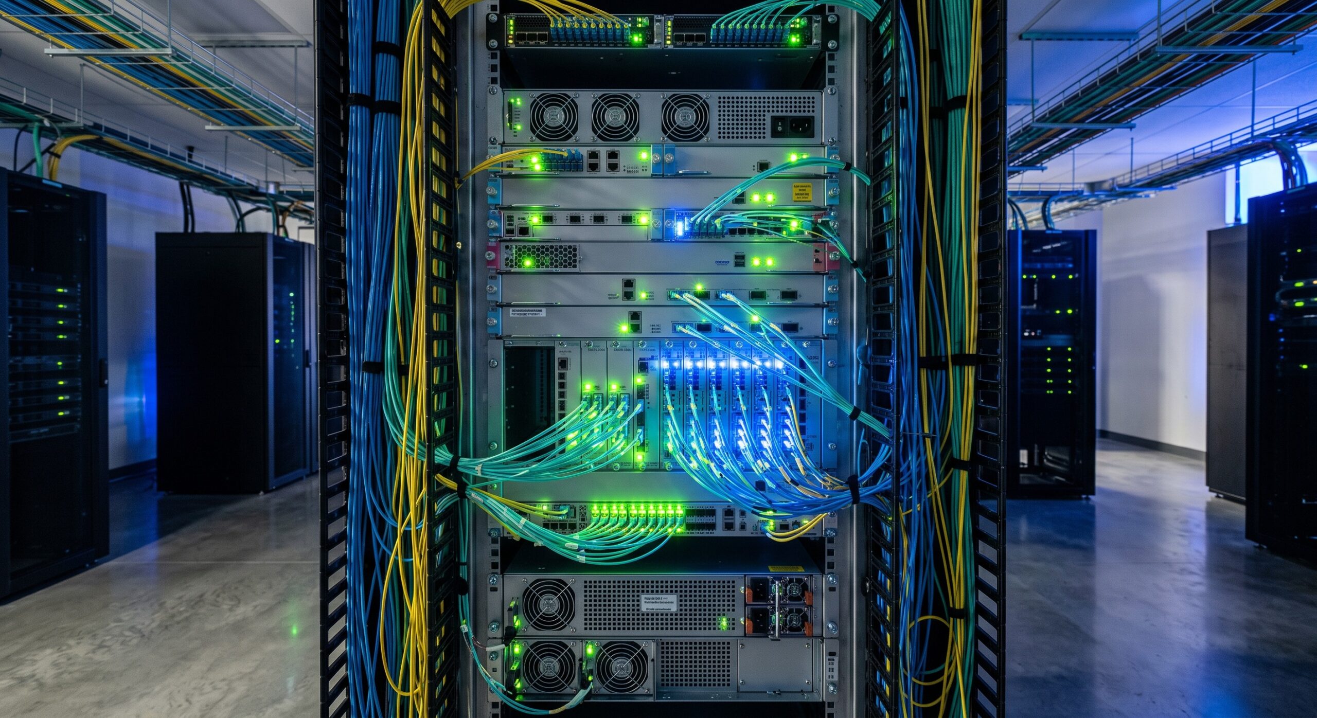
Dark Fiber Lighting Hardware: Core Architecture
Lighting dark fiber requires more than plugging in a transceiver. Modern deployments demand a sophisticated hardware stack that includes DWDM/CWDM multiplexers, optical amplifiers, and transponders/muxponders. A fundamental decision point is between Direct Point-to-Point optics and Wavelength Division Multiplexing (WDM) architectures . For links under 10km, standardized 10G/25G SFP+ or QSFP optics may suffice. However, for metro and long-haul routes exceeding 100 km—a common scenario in dark fiber leases—optical amplifiers and advanced forward error correction (FEC) are mandatory .
Optical Signal-to-Noise Ratio (OSNR) and Reach
Unlike lit services where the carrier manages signal integrity, dark fiber lighting places the responsibility for OSNR budgeting solely on the enterprise. Hardware must be selected based on precise loss budgets, which are influenced by the fiber’s attenuation coefficient (typically 0.25 dB/km at 1550nm) and the number of physical connectors or splices. WDM solutions, such as those offered for Data Center Interconnect (DCI), often utilize coherent optics that can compensate for chromatic dispersion and polarization mode dispersion (PMD) via internal ASICs, pushing reach beyond 400km without regeneration .
Carrier-Grade Redundancy
High-availability architectures rely on 1+1 Optical Protection Switching. This involves deploying dual fiber pairs or utilizing a diverse route to ensure that if a fiber cut occurs, the hardware switches traffic to the secondary path within sub-50 millisecond timelines, meeting stringent ITU-T G.841 standards for SDH/SONET protection. Hardware platforms must support these protection schemes natively within their line cards .
| Key Parameter | Technical Specification |
|---|---|
| Wavelength Support | ITU-T G.694.1 (DWDM) / G.694.2 (CWDM) |
| Channel Spacing | 50GHz (96 Channels) or 100GHz |
| Max Reach (w/ Amplification) | 100km+ (Coherent Optics support up to 400km) |
| Protection Switching | |
| Line Rate (Max per Wavelength) | 100G/200G/400G/800G (Coherent) |
| MTBF (Hardware) | > 100,000 Hours (Carrier Grade) |
Technical Specifications and Performance Metrics
Wavelength Grid and Density
Adherence to the ITU-T G.694.1 DWDM grid is critical for interoperability. High-density systems support 96 channels at 50GHz spacing, allowing for massive scalability on a single fiber pair. For enterprises that require ultimate security, Layer-1 hardware encryption is available on transponder line cards, scrambling data at line rate without introducing latency .
Latency Considerations
Dark fiber offers the theoretical lowest latency because it removes the intermediate switching hops typical of MPLS or IP networks. However, the dark fiber lighting hardware can introduce latency due to FEC processing and optical-electrical-optical (OEO) conversions in transponders. For ultra-low latency environments, such as high-frequency trading networks, hardware must utilize direct optics or low-latency FEC modes (e.g., G.709 standard with reduced interleaving) to ensure end-to-end latency remains in the microsecond range.
Deployment Scenarios: Maximizing ROI
One of the primary drivers for dark fiber solutions is Total Cost of Ownership (TCO). By leasing Indefeasible Right of Use (IRU) dark fiber and purchasing the lighting hardware outright, enterprises can amortize CapEx over 10-20 years, significantly reducing OpEx compared to recurring high-bandwidth lit service fees . This is particularly compelling for organizations connecting multiple Data Centers (DCI) or building geographically diverse routes.
For instance, building a low-latency route between NYC and Ashburn—the world’s largest data center market—requires specific hardware capable of driving signals over hundreds of kilometers. Recent acquisitions and expansions in the fiber market highlight a resurgence in demand for these tailored routes, driven by AI and high-speed streaming, necessitating hardware that can scale from 100G to 800G wavelengths over the same dark fiber pair .

Conclusion: Building a Future-Proof Foundation
The success of a dark fiber lighting project hinges on rigorous hardware selection. Network architects must prioritize platforms offering modular scalability, low-latency ASIC-based forwarding, and robust protection mechanisms to meet carrier-grade SLAs (99.999% availability). As data consumption increases, dark fiber provides the dedicated, scalable bandwidth required for 5G backhaul, AI compute clusters, and secure government networks . By investing in the right transmission hardware today, enterprises unlock the full potential of their fiber assets, ensuring a resilient, high-performance network for the next decade.

Leave a comment