
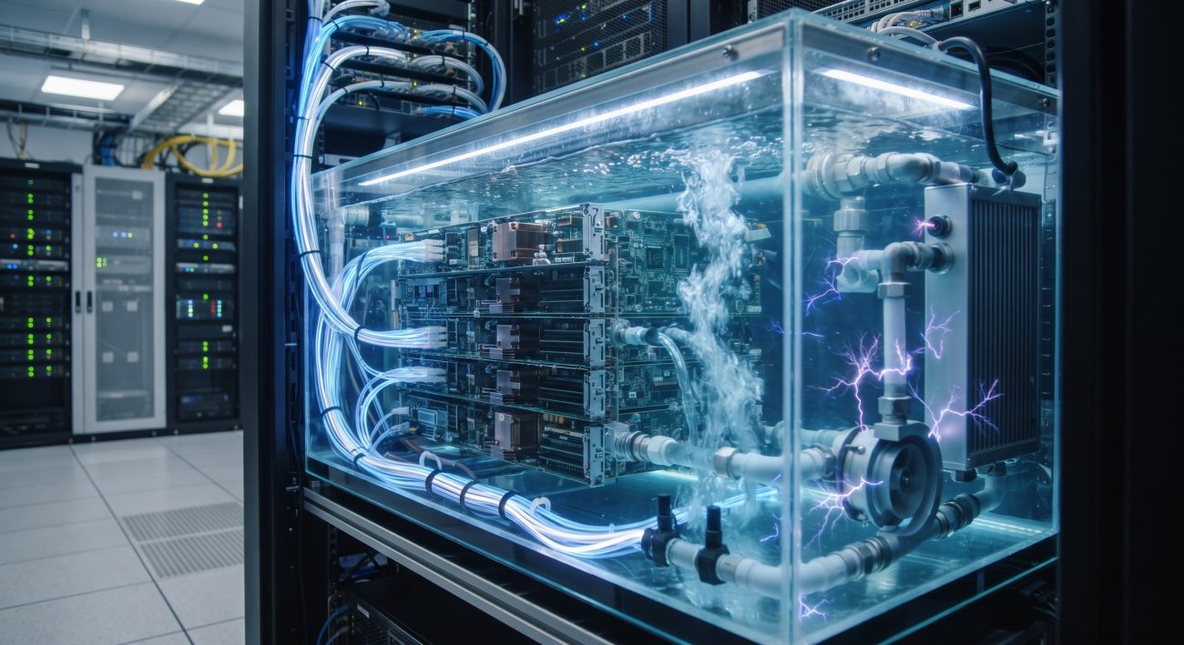
SLA Demands and the Hidden Threat in Dielectric Loops
Carrier-grade telecom infrastructure operates under five-nines availability mandates, where a single unplanned downtime event can cascade into SLA penalties exceeding $500,000 per hour for Tier-1 core routing sites. While single-phase immersion liquid cooling has emerged as the definitive thermal solution for 500W+ ASIC line cards and 25 kW+ rack densities, a subtle electrochemical phenomenon threatens the very reliability gains the technology promises: electrostatic charge generation within the fluid loop. Unlike air-cooled systems where ESD is mitigated through humidity control and grounded chassis, immersion modules introduce a flowing dielectric medium that can accumulate and transport static charge directly across bare-metal components. This analysis examines the failure mechanisms, quantifies the MTBF impact, and provides hardened engineering controls for carrier-grade deployments.
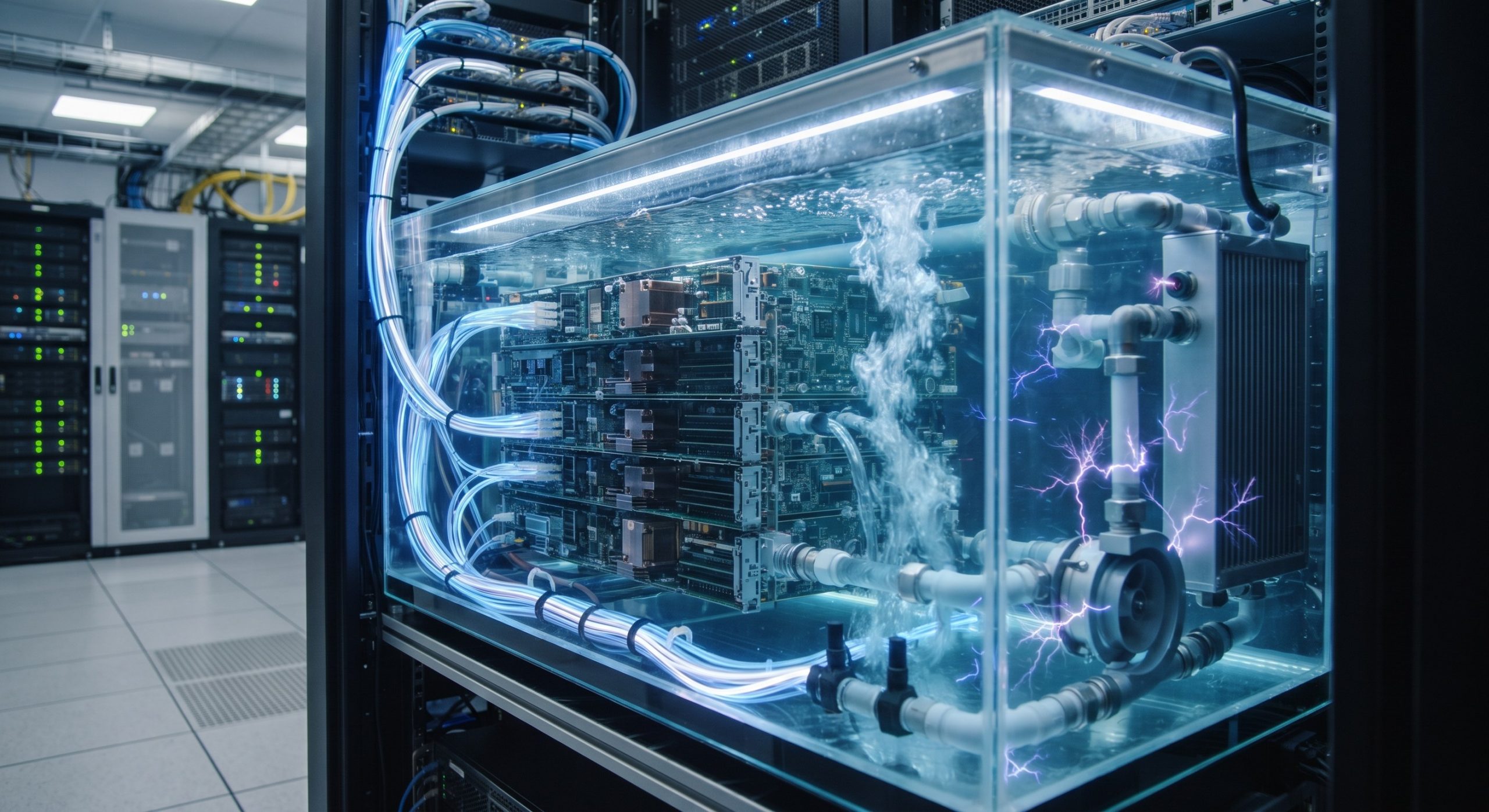
Dual-Engine Failover Architecture and Charge Accumulation Pathways
Flow Electrification Mechanisms in Hydrocarbon Dielectrics
The generation of electrostatic charge in single-phase immersion loops is not a theoretical concern—it is a well-documented phenomenon in hydrocarbon fluid systems dating back to the 1970s petroleum industry. When synthetic hydrocarbon or mineral oil dielectrics flow across non-metallic surfaces (PTFE tubing, polycarbonate tank walls, epoxy PCBs), triboelectric charging occurs as electrons are stripped from the stationary material and entrained in the fluid stream. The magnitude of charge generation scales with flow velocity, fluid conductivity, and the surface area of dissimilar materials in contact. In a typical 10 kW immersion module circulating 1.5–3.0 L/min per kW through a manifold distribution system, charge densities can reach levels sufficient to produce several kilovolts of potential on isolated metallic components if grounding paths are compromised.
The dual-engine failover architecture inherent to carrier-grade immersion modules introduces additional complexity: redundant pumps operating in active-standby configuration create transient flow discontinuities during failover events. These pressure surges can momentarily increase flow velocity through restrictive manifold orifices, amplifying charge separation at dielectric-to-metal interfaces. Without proper dissipation, accumulated charge can discharge through sensitive 400G/800G optical transceiver front-ends or ASIC SerDes lanes, producing latent failures that evade standard burn-in screening.
MTBF Degradation and Latent Failure Modes
Field data from immersion-cooled telecom line cards indicates that unmitigated electrostatic discharge events degrade module MTBF from the nominal 250,000+ hours to as low as 85,000 hours in poorly grounded installations. The failure signature is insidious: rather than catastrophic destruction of the ASIC die, ESD events produce gate oxide wear-out in the transceiver DSPs and thin-film resistor drift on line card power management ICs. These parametric shifts manifest as intermittent link flaps under thermal stress, creating troubleshooting nightmares for NOC teams accustomed to hard failures.
Grounding integrity is further complicated by the trend toward non-metallic tank construction for corrosion resistance and weight reduction. Polycarbonate and acrylic tanks, while chemically compatible with hydrocarbon dielectrics, are dielectric insulators that prevent charge dissipation through the enclosure. The Open Compute Project immersion requirements explicitly mandate that electrostatic generation in dielectric fluids shall be considered and documented to assure adequate dissipation of static charge. Compliance with this requirement demands deliberate grounding electrode design rather than reliance on incidental metallic contact.

Core Parameters: Charge Mitigation and Reliability Specifications
The following table summarizes the critical engineering parameters governing electrostatic charge control in carrier-grade single-phase immersion modules, derived from IEC 61340-5-1 test methodologies and field-validated deployment data.
| Key Parameter | Technical Specification |
|---|---|
| Dielectric Fluid Volume Resistivity | ≥ 5 × 10¹³ Ω·cm (charge mobility without leakage) |
| Static Decay Half-Life (IEC 60093) | ≤ 10 seconds (qualified); ≤ 1 second (excellent) |
| Grounding Plate Resistance to Earth | |
| Maximum Tolerable Charge Potential | |
| Module MTBF (Properly Grounded) | > 250,000 hours |
| Module MTBF (Ungrounded/Compromised) | ~85,000 hours (field-observed) |
| Pump Failover Transient Voltage Spike |
Mission-Critical Deployments and Hardened Grounding Topologies
Immersion-Specific Grounding Architecture
Effective electrostatic dissipation in immersion modules requires a layered grounding strategy that addresses charge generation at the source, provides low-impedance paths to earth, and monitors for degradation over the 10–15 year service life of carrier-grade equipment. The primary control is a grounded metallic plate or strip positioned in the flow path at the lowest point of the tank, maximizing fluid contact surface area and ensuring that charge-laden dielectric passes over the grounded conductor before reaching sensitive electronics. For non-metallic tanks, this plate becomes the sole reference ground for the entire fluid volume and must be bonded to the rack grounding busbar with < 0.1 Ω resistance.
Secondary controls include conductive additives in the dielectric formulation to increase charge decay rates. Modern hydrocarbon fluids optimized for immersion cooling achieve static decay half-lives of ≤ 10 seconds under IEC 60093 test conditions, a 100-fold improvement over unadditized mineral oils. However, operators must verify that additive packages remain stable across the fluid’s service life—thermal cycling at 65°C junction temperatures can degrade conductivity enhancers, silently eliminating the dissipation pathway.
Monitoring and Preventive Maintenance Protocols
Carrier-grade deployments should implement continuous electrostatic potential monitoring at critical nodes: the pump discharge manifold, the heat exchanger inlet, and the tank headspace. A floating-electrode sensor referenced to chassis ground can detect charge accumulation exceeding 500 V—well below the 2 kV threshold for transceiver damage—and trigger maintenance alerts before latent failures occur. Quarterly fluid sampling should verify volume resistivity remains within 5×10¹³ to 10¹⁶ Ω·cm, the range associated with adequate charge mobility without excessive leakage current.
During pump failover testing, operators should monitor for transient voltage spikes on the grounding reference. A properly designed system will exhibit < 50 V deviation during the 200–500 ms failover window; larger excursions indicate insufficient grounding electrode surface area or excessive flow restriction in the standby pump path.
Final Assessment: Reliability Engineering Beyond Thermal Performance
The thermal case for single-phase immersion liquid cooling in carrier-grade telecom hardware is unambiguous: 1,200× the heat capacity of air, junction temperature control within ±2°C across 500W ASICs, and the elimination of fan-induced vibration and dust ingress. However, the reliability case depends equally on disciplined electrostatic management. An immersion module that achieves 105°C junction temperatures but accumulates 3 kV of static charge on its optical cage is not a carrier-grade solution—it is a deferred failure waiting to manifest under peak traffic load.
Engineering teams specifying immersion cooling for core routing or edge aggregation sites must treat grounding architecture, fluid conductivity specifications, and charge monitoring as first-class design requirements alongside thermal resistance and flow rate. The MTBF dividends—from 85,000 hours to beyond 250,000 hours—justify the incremental design effort and validate the transition from air-cooled to immersion-cooled infrastructure for the 800G and 1.6T eras.
Leave a comment