

The Non-Negotiable Need for Power Resilience in Modern Networks
In the realm of carrier-grade and enterprise networking, a switch is only as reliable as its power supply. The humble power subsystem is often the single point of failure that can bring down an entire data center fabric or core routing domain. As network architects, we design for high availability, but without a meticulously architected switch power supply redundancy strategy, hardware Mean Time Between Failures (MTBF) metrics become irrelevant. This guide delves into the architectural frameworks, operational modes, and technical specifications that define resilient power design, leveraging insights from field deployments and vendor reference architectures to ensure your network achieves its promised five-nines availability.

Understanding Redundancy Architectures: Beyond the Marketing Specs
At its core, switch power supply redundancy is a system of parallel power modules designed to ensure uninterrupted DC output to the backplane and line cards. The fundamental architecture relies on load-sharing and failover mechanisms managed by a dedicated power management controller (PMC). The primary goal is to mitigate the catastrophic impact of a single power supply failure, which, as defined in foundational studies, constitutes the weakest link in system reliability due to the high electrical stress on semiconductor switches .
Redundancy Modes Explained
Modern chassis-based systems like the Cisco Nexus 9000 and Catalyst 6500 series support distinct operational modes, each with specific TCO and resilience implications .
- N+1 (Power Supply Redundancy / ps-redundant): This is the most common configuration for high availability. In this mode, one power supply acts as a dedicated standby. The system’s total available power is capped at the capacity of a single supply (assuming equal wattage). When one unit fails, the standby seamlessly takes over. This mode is ideal for environments where rack space and power feed diversity are secondary to component failure protection. A critical operational requirement is that all installed power supplies must have the same wattage; otherwise, the system will disable the lower-wattage unit to maintain the N+1 state .
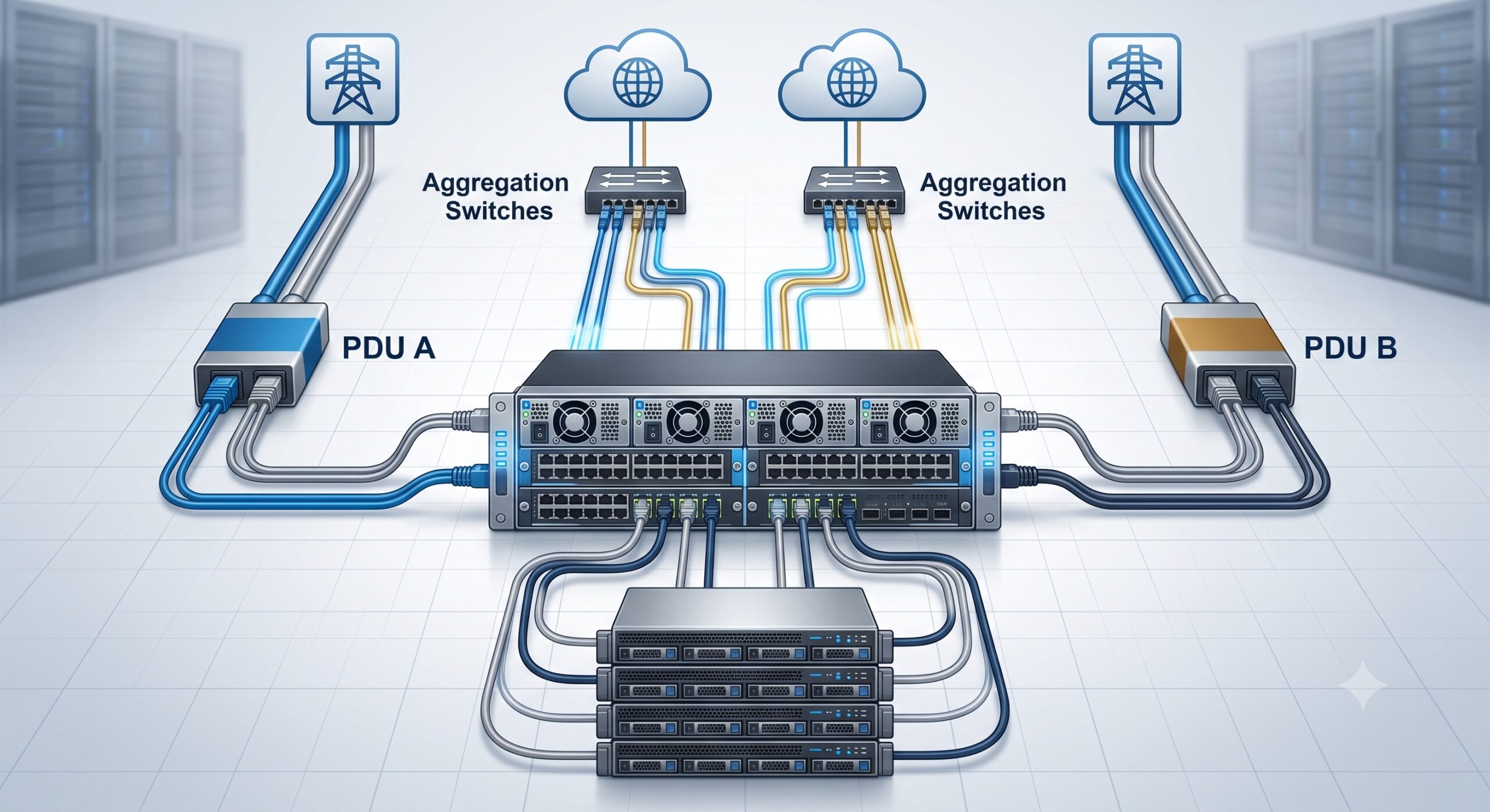
- Input Source (Grid) Redundancy (insrc-redundant): This mode provides protection against the loss of an entire power feed or grid. It divides the installed power supplies into two categories: “Available” and “Reserved”. For example, in a 4-supply system, half are allocated to the active power bus. This design ensures that the switch can continue operating even if one power grid (and its associated supplies) fails, as long as the “Reserved” supplies remain active on the secondary grid .
- Combined Mode (Non-Redundant): This mode aggregates the total wattage of all installed power supplies to maximize the power budget for high-density line cards, such as the 36-port 400G line cards. However, this sacrifices redundancy entirely. If a supply fails and the remaining capacity cannot support the current load, the system will forcibly power down lower-priority modules and PoE devices, potentially causing traffic disruption .
Configuration and Operational Parameters
The implementation of switch power supply redundancy is managed via software configuration and verified through hardware state monitoring. The industry-standard Simple Network Management Protocol (SNMP) MIBs (e.g., CONFIG-MIB) define objects like ‘chHWPowerConfigurationAdmin’ to explicitly set the desired redundancy state to either ‘redundant(1)’ or ‘noRedundancy(2)’ .
Field observations from Cisco Nexus 9500 deployments highlight a common operational pitfall: the ‘Pwr-Denied’ state. This occurs when the power management system miscalculates the remaining power budget during a redundancy mode reconfiguration. Engineers may encounter a scenario where the total capacity physically installed exceeds the allocated budget, yet the system refuses to switch to ‘ps-redundant’ mode, reporting an “Insufficient capacity” error . This typically happens when the system’s power allocation algorithm reserves power for future fabric modules or specific line card power-on sequences, artificially inflating the allocated budget beyond the actual draw. It is a critical reminder that power calculations must include steady-state draw and peak power-on current for all modules.
| Redundancy Mode | Power Capacity Basis | Key Operational Feature | Example Use Case |
|---|---|---|---|
| Combined (Non-Redundant) | Sum of all supplies | Maximum power for high-density line cards | Lab environments, short-term testing |
| N+1 (PS-Redundant) | Capacity of one supply | Seamless failover on component failure | Enterprise core, Data center spine |
| Input Source (Grid Redundant) | Capacity of one grid/feed set | Protection against AC feed loss | Carrier central offices, Tier 4 DCs |
| Full Redundancy | Capacity of one supply on one grid | Combination of N+1 and Grid protection | Mission-critical financial networks |
Carrier-Grade Reliability: MTBF, Load Balancing, and Compliance
For telecommunications and mission-critical enterprise networks, the MTBF of the power supply subsystem is a non-negotiable metric. Utilizing switch power supply redundancy with load balancing not only provides failover capability but also reduces stress on individual components. By evenly distributing current draw across the active modules, the system reduces thermal stress and extends operational life.
Traffic Shaping and Power Distribution
While often overlooked, the power distribution topology interacts with the ASIC forwarding plane. In the event of a power supply failure and subsequent module shut down (in combined mode), the system must gracefully manage traffic failover. The Cisco Catalyst 6500 architecture defines a fixed power-down order: PoE devices are shut down first, followed by line cards in descending slot order, bypassing supervisor engine and fabric modules . This deterministic behavior ensures that control plane integrity is preserved even during severe power deficits.
From a compliance perspective, modern high-density power supplies, such as the 3000W AC units used in the Nexus and MDS series, must adhere to stringent IEEE and ITU-T standards for electromagnetic compatibility (EMC) and safety. The mean time between failures for these units typically exceeds 100,000 hours under nominal operating conditions, but this drops significantly if the environmental temperature exceeds the 40°C threshold, making thermal management a direct contributor to system MTBF.
Verdict: The Architectural Impact of Redundancy Design
The choice between power supply redundancy modes is a strategic architectural decision. For Tier 4 data centers requiring fault tolerance against power feed failures, implementing Input Source (Grid) redundancy is essential. For standard enterprise core networks, N+1 (Power Supply) redundancy provides the necessary hardware resilience. However, engineers must be wary of the “Pwr-Denied” traps common in high-density chassis. Accurate capacity planning requires validating the Total Power Allocated (budget) against the Total Power Capacity based on the configured mode .
Ultimately, a robust switch power supply redundancy strategy is about balancing physical power capacity, redundancy requirements, and operational management. By enforcing strict wattage matching for supplies in redundant configurations and regularly monitoring power budgets via SNMP, network architects can fortify their infrastructure against the most common yet devastating physical layer failures. The operational goal is clear: ensure that the only thing that fails is the power supply itself, not the service it powers.
Conclusion
Implementing a resilient power architecture is not a ‘set it and forget it’ task. It demands a continuous cycle of capacity planning, environmental monitoring, and fault simulation. By thoroughly understanding the nuances of N+1, Grid, and Combined modes, and rigorously validating power budgets against line card configurations, you ensure that your network hardware delivers the carrier-grade reliability promised by its MTBF ratings. A well-designed switch power supply redundancy strategy is the foundational pillar upon which a high-availability network is built, protecting against the inevitable hardware failures that occur over a network’s operational life.

Leave a comment