

EXECUTIVE SUMMARY
This document serves as the definitive technical reference for the deployment and operational management of fiber drop cable splicing, tailored for carrier-grade access networks. As network densification accelerates and fiber-to-the-premises (FTTP) deployments push deeper into diverse environmental terrains, the integrity and performance of drop cable splicing have become paramount. This datasheet details the comprehensive suite of hardware, enclosures, and field procedures engineered to ensure minimal insertion loss, long-term environmental sealing, and rapid deployment, all while adhering to Telcordia GR-326 and GR-3120 core standards. Our solution provides a unified platform for fusion splicing, mechanical splicing, and pre-connectorized drop terminations, designed to reduce OPEX and increase network reliability.

ARCHITECTURE & CHASSIS DESIGN
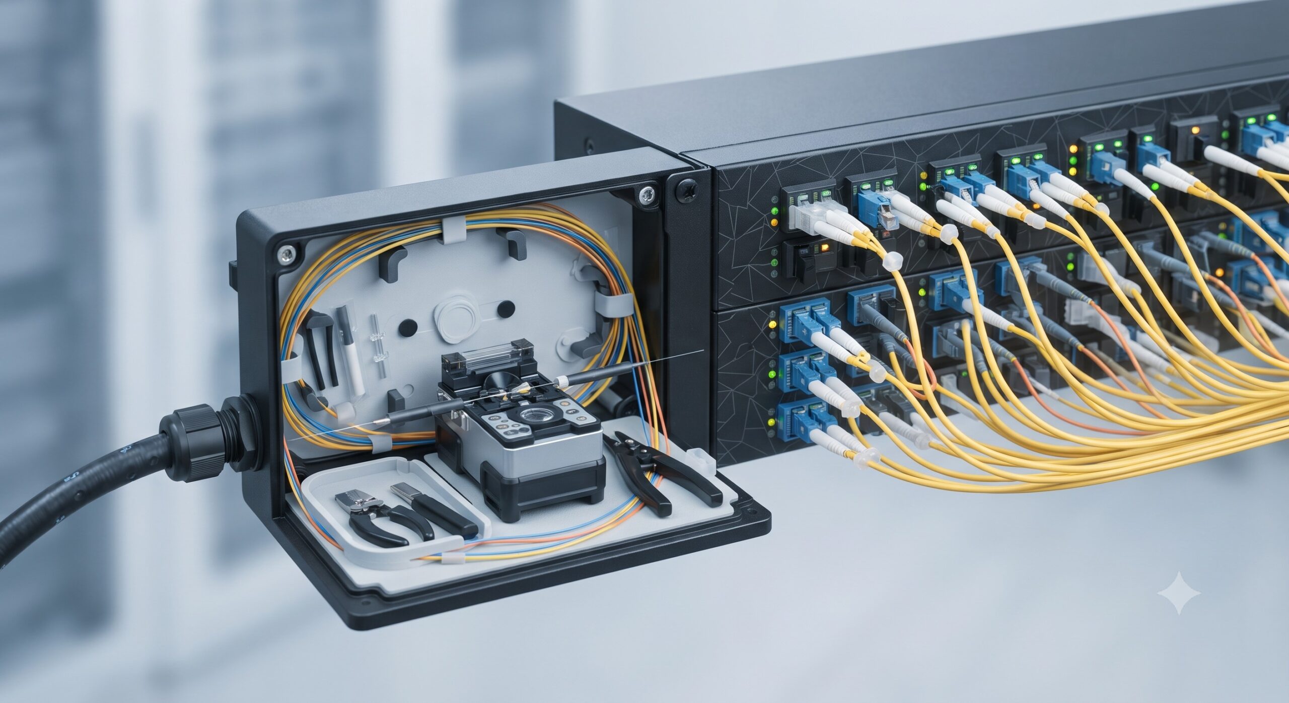
The fiber drop cable splicing architecture is built upon a modular, field-proven platform designed for both aerial and buried plant environments. The core of the system comprises a high-strength, corrosion-resistant enclosure available in multiple form factors: a compact 2-port dome for pedestal mounting, a mid-size 6-port inline splice closure for hand-hole or strand mounting, and a high-density 12-port cabinet for FTTA and MDU applications. The chassis design features a unique “splice tray stacking” mechanism that allows for up to 144 individual fusion splices (using 12-fiber ribbon or single-fiber mass fusion) within a single closure. A central gel-sealed entry port system accommodates drop cables ranging from 3.0mm to 16.0mm in diameter, utilizing a patent-pending “O-ring plus compression seal” technology that provides a waterproof rating of IP68 (1.5 meters for 72 hours). The internal organizer provides a clear, bend-radius protected path, separating the incoming feeder cable, the splice point, and the outgoing drop cables, with dedicated storage for slack loops to facilitate future re-entry without disturbing active splices.
HARDWARE FEATURES
Field Termination Kits: Our premium splice-on-connector (SOC) kits support SC, LC, and ST form factors, featuring pre-polished zirconia ceramic ferrules with an APC (Angled Physical Contact) polish for optimal return loss (
Parameter
Specification
ORDERING OPTIONS
The model numbering convention follows a standardized SKU logic: SS – [Port Count] – [Splice Type] – [Environment]. A comprehensive ordering matrix is available below to facilitate procurement.
– Base Closures: SS-2P (2-port pedestal), SS-6P (6-port aerial/buried), SS-12C (12-port cabinet).
– Splice Trays: ST-24S (24 single splices), ST-12R (12 ribbon splices, 12-fiber ribbon).
– Accessories: MS-SOC-KIT (Mechanical SOC kit, 10 units), FS-SOC-KIT (Fusion SOC kit, 10 units), CL-200 (Closure re-entry tool kit).
– Fusion Splicers: FTTH-3000 (Core alignment, with battery), FTTH-1000 (Fixed V-groove, entry-level).
Each standard closure order includes: 1x Main Enclosure, 2x Cable Entry Glands (expandable), 1x Base Splice Tray (empty), 1x Grounding Kit, and comprehensive installation manual. Extended warranty packages (5-year and 10-year) are available for critical infrastructure projects.
📥 Download Technical Specification
Click the button below to view or download the full official PDF datasheet.

Leave a comment