
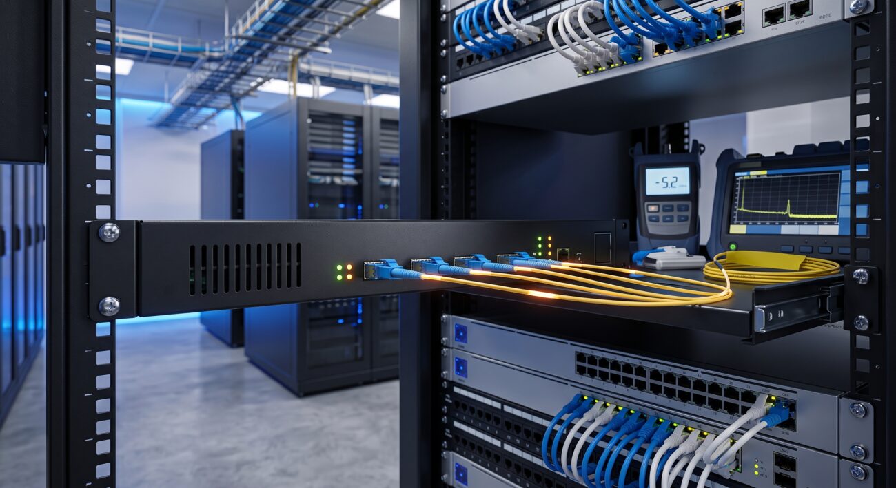
Overview & Thematic Scope
Welcome to our comprehensive FAQ on Erbium-Doped Fiber Amplifier (EDFA) optical amplifier specifications. This guide addresses the most critical technical questions asked by network engineers, procurement specialists, and system integrators. From optical gain and noise figure to connector types and operational limits, we cover the key specifications that determine the performance, reliability, and compatibility of EDFAs in dense wavelength division multiplexing (DWDM) and long-haul networks. The following expert answers are designed to clarify both pre-sales considerations and post-sales support issues.
Frequently Asked Questions
- Q1: What are the most critical EDFA optical amplifier specifications I must evaluate for a long-haul DWDM system?
- The most critical EDFA specifications for long-haul DWDM are the small-signal gain, noise figure, and saturation output power. The small-signal gain (typically 15-40 dB) determines the amplification factor for weak signals, while the noise figure (ideally below 5 dB) directly impacts the optical signal-to-noise ratio (OSNR) at the receiver. Equally important is the saturation output power (Psat), which defines the maximum output power before gain compression occurs, influencing the amplifier’s ability to handle multiple channels. These parameters collectively dictate the amplifier’s ability to extend transmission distances and support high channel counts.
- Q2: How do I interpret the gain flatness specification across the C-band and L-band?
- Gain flatness refers to the variation in amplifier gain across a specified wavelength range, typically expressed in decibels (dB) as a peak-to-peak or root-mean-square (RMS) value. For C-band EDFAs (1530-1565 nm), a standard specification is a flatness of ±0.5 dB to ±1.5 dB over the entire band. This specification is crucial because non-uniform gain leads to channel power imbalances in DWDM systems, which can degrade OSNR and require expensive gain-flattening filters. Our EDFA catalogs provide detailed gain flatness curves at various input powers to help you predict system performance under real-world conditions.
- Q3: What are the typical input power range and maximum total input power for an EDFA?
- The typical input power range for a standard EDFA is -20 dBm to +5 dBm per channel. However, the maximum total input power is more critical and usually specified as an absolute maximum (e.g., +20 dBm total aggregate power) to prevent optical damage. Exceeding this maximum can cause permanent damage to the pump laser or erbium-doped fiber. Always ensure your system’s total launch power into the EDFA remains within the manufacturer’s specified limit. For high-power EDFAs used in CATV or dense metro networks, the total input power may be higher, but this is always accompanied by higher gain values.
- Q4: How does the noise figure (NF) of an EDFA affect system performance, and what is a good NF value?
- The noise figure quantifies the degradation in OSNR caused by the amplifier; a lower NF is always better. For a high-performance EDFA, a typical NF at the operating point is between 4.0 dB and 5.5 dB. A lower NF ensures that amplified spontaneous emission (ASE) does not overwhelm the signal, thereby maintaining a healthy OSNR margin for the downstream receiver. In practice, a 1 dB reduction in NF can increase transmission reach by up to 10-20%, making it a primary selection criterion for very long-haul systems. Our EDFA series is designed to achieve industry-leading low NF values across the entire gain range.
- Q5: What are the standard optical interface connector types and fiber types compatible with these EDFA units?
- Our EDFA units are available with standard connector types including SC/APC (angled physical contact), FC/APC, and LC/UPC, with SC/APC being the most common for low back-reflection applications required in high-power DWDM systems. The fiber type is typically single-mode fiber (SMF) compliant with ITU-T G.652, but some models are available with G.655 (non-zero dispersion-shifted fiber) compatibility. Always verify the connector polish type; APC connectors are strongly recommended for EDFAs to minimize return loss (
- Q6: What are the typical thermal and environmental operating limits for an EDFA, and what cooling is required?
- Standard EDFA operating temperature ranges are 0°C to 45°C (ambient) for commercial-grade units and -5°C to 60°C for industrial/hardened versions. The thermal design is critical because EDFA pump lasers (typically 980nm or 1480nm) and the erbium-doped fiber itself are temperature-sensitive. Most units employ forced-air cooling (built-in fans) with sufficient thermal headroom to maintain internal temperatures below 60°C. For extreme environments, such as unstaffed POPs (points of presence), we offer enhanced cooling options or passive thermal conduction designs. Adhering to the specified humidity limits (typically 5% to 85% non-condensing) is also essential for long-term reliability.
- Q7: How do I configure the gain and output power settings, and what is the difference between AGC and APC modes?
- Our EDFA units support two primary control modes: Automatic Gain Control (AGC) and Automatic Power Control (APC). In AGC mode, the amplifier maintains a constant gain regardless of input power fluctuations, which is ideal for DWDM systems where channel count or input power may vary. In APC mode, the amplifier maintains a constant total output power, which is useful for applications where a fixed launch power is required. Configuration is performed via the front panel display, RS-232 serial port, or SNMP management interface. We recommend AGC mode for most DWDM applications as it provides superior stability for the overall link budget.
- Q8: What are the common alarm and status monitoring features available in the EDFA, and how do I interpret them?
- Standard EDFA units are equipped with a comprehensive set of alarms and monitoring points: Input Power Loss Alarm, Output Power Degradation, Temperature Warning, and Pump Laser Current/Voltage status. These are typically provided as Form-C relay contacts for connection to external alarm monitoring systems, and via software-based traps. For example, the “Input Power Loss” alarm (triggered when input power drops below -30 dBm) indicates a potential fiber break or upstream transmitter failure. Regular monitoring of the pump current can provide early warning of laser aging, enabling proactive maintenance before a full system failure occurs.

Leave a comment