Why Is GPON Popular in FTTH Network?
GPON (Gigabit passive optical network) is defined by ITU-T recommendation series G.984.x. It can transport not only Ethernet but also ATM and TDM (PSTN, ISDN, E1, and E3) traffic. It represents an increase in bandwidth compared with ATM PON (APON) and broadband PON (BPON). Supporting triple-play services, high bandwidth and long reach (up to 20 km), GPON can be applied in many scenarios, especially in FTTx networks. Besides, GPON customers are typically homes or small businesses. Since the GPON technology can deliver data, voice, and IP video, it is suitable and popular for fiber to the home (FTTH) transmission. In FTTH application, the passive optical network (PON) based FTTH network is a point-to-multipoint, fiber to the premises network architecture where unpowered optical splitters are used to enable a single optical fiber to serve 32-128 premises. The following text will focus on components and architecture of GPON FTTH access network.
Components of GPON FTTH Access Network
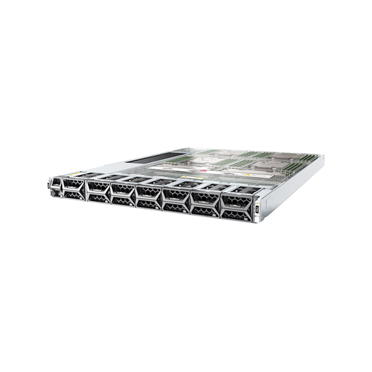
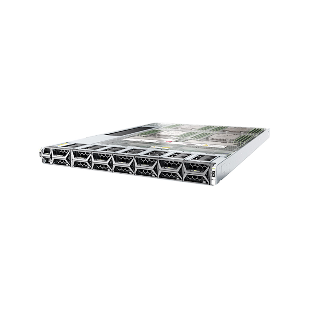
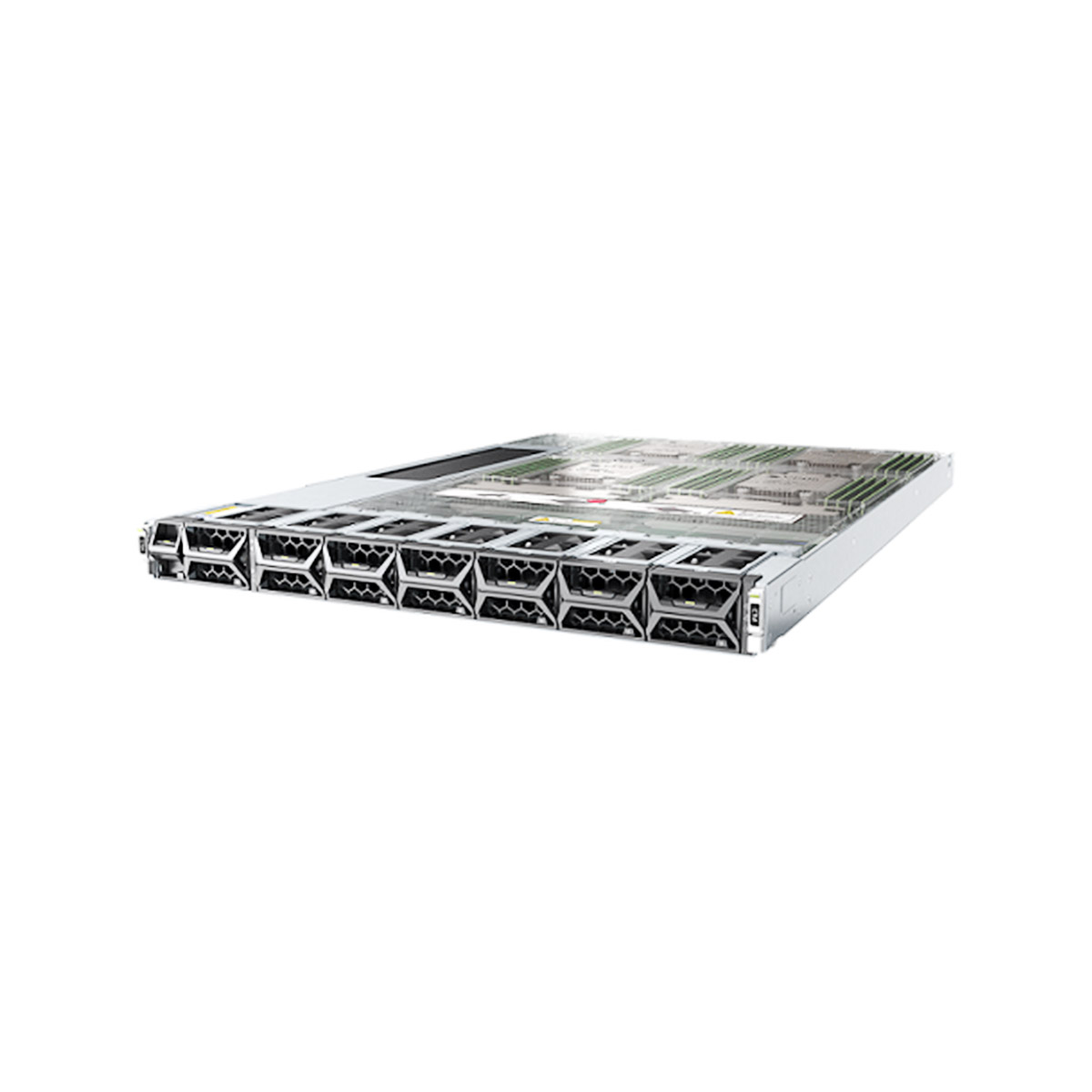
In a GPON FTTH access network, there are three main components: optical line terminal (OLT), like MA5608T, MA5800-X7, MA5800-X15, optical splitters and optical network terminal (ONT), like HG8546M, EG8145V5, HN8346V5.
OLT (Optical Line Terminal)
OLT is a device that serves as the service provider endpoint of a passive optical network. It is an active Ethernet aggregation device that is usually located in a data center or the main equipment room. It is the engine that drives the FTTH system. An OLT converts the optical signals to the electrical signals and presents them to a core Ethernet switch. The OLT replaces multiple layer 2 switches at distribution points. OLT distributing signal is connected with backbone cabling or horizontal cabling through optical splitters, which are connected to the optical network terminal at each work area outlet.
Optical Splitter
The optical splitter splits the power of the signal. That is to say, each fiber link entering the splitter may be split into a given number of fibers leaving the splitter. Usually, three or more levels of fibers correspond to two or more levels of splitters. This enables sharing of each fiber by many users. The passive optical splitter has the characteristics of broad operating wavelength range, low insertion loss and uniformity, minimal dimensions, high reliability, and supporting network survivability and protection policy.
ONT (Optical Network Terminal)
ONT is deployed at the customer’s premises. It is connected to the OLT by means of optical fiber and no active elements are present in the link. In GPON, the transceiver in the ONT is the physical connection between the customer premises and the central office OLT.
The architecture of GPON FTTH Network
With a tree topology, GPON maximizes the coverage with minimum network splits, thus reducing optical power. An FTTH access network comprises five areas, which are a core network area, a central office area, a feeder area, a distribution area, and a user area/customer premises
Core Network
The core network includes the internet service provider ISP equipment, PSTN (public switched telephone network, packet-switched or the legacy circuit-switched), and cable TV provider equipment.
Central Office
The main function of the central office is to host the OLT and ODF (optical distribution frame) and provide the necessary powering. Sometimes it might even include some of the components of the core network.
Feeder Network
The feeder area extends from ODF in the central office (CO) to the distribution points. These points, usually street cabinets, are called fiber distribution terminals (FDTs) where level-1 splitters usually reside. The feeder cable is usually connected as ring topology starting from a GPON port and terminated into another GPON port as shown in the picture above to provide type B protection.
Distribution Network
Distribution cable connects level-1 splitter (inside the FDT) with a level-2 splitter. Level-2 splitter is usually hosted in a pole-mounted box called fiber access terminal (FAT) usually placed at the entrance of the neighborhood.
User Area
In the user area, drop cables are used to connect the level-2 splitter inside the FAT to the subscriber premises. For ease of maintenance, usually, an aerial drop cable is terminated at the entrance of the subscriber home with a terminal box (TB), then an indoor drop cable connects the TB to an access terminal box (ATB) residing inside the home. Finally, a patch cord connects the ONT to the ATB.

Leave a comment