

EXECUTIVE SUMMARY
The Immersion Liquid Cooling Tank Seal Integrity and Ingress Standards solution establishes the definitive engineering baseline for single-phase and two-phase immersion cooling enclosures deployed in carrier-grade telecom and datacenter environments. This document specifies the mandatory seal architectures, material compatibility requirements, ingress protection ratings, and verification protocols that ensure long-term dielectric fluid containment, electrical isolation, and operator safety. The platform addresses the critical failure modes of gasket degradation, differential pressure stress, and fluid migration, delivering a validated framework for tank manufacturers, integrators, and network operators.

ARCHITECTURE & CHASSIS DESIGN
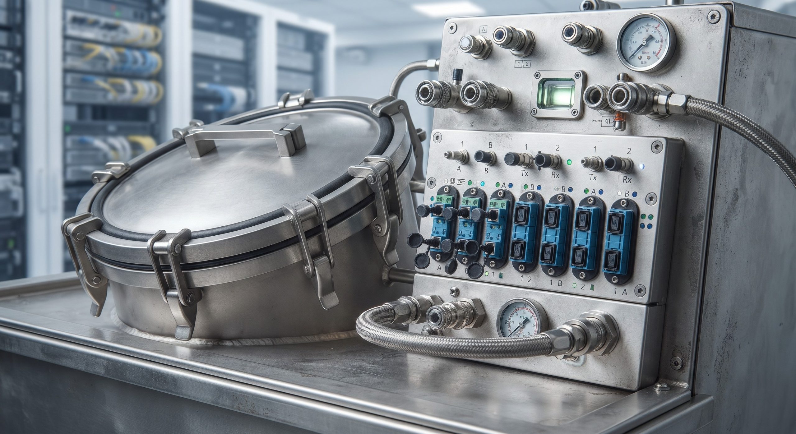
The immersion tank seal architecture employs a multi-layer containment strategy. Primary sealing is achieved through a compression-molded fluoropolymer gasket seated in a machined groove on the tank flange, providing a defined compression set and resistance to dielectric fluids, glycols, and refrigerants. Secondary containment is provided by a welded or continuously cast tank body with a minimum wall thickness of 3.0 mm for aluminum and 2.0 mm for stainless steel, eliminating seam porosity. A tertiary weep-channel and leak-detection trough is integrated into the base perimeter, allowing visual or sensor-based detection of primary seal breach before fluid reaches external surfaces. The lid interface incorporates a torque-limited fastening pattern with captive stainless steel hardware and a specified bolt spacing not exceeding 150 mm to maintain uniform gasket loading. Cable and fiber ingress points are sealed using compression fittings rated to IP68 and compatible with the dielectric fluid chemistry. The chassis design accommodates thermal expansion of the fluid volume through a dedicated expansion reservoir or ullage space of at least 8% of total tank volume, preventing overpressure on the lid seal.
HARDWARE FEATURES
Seal integrity features include a dual-gasket lid design with an inner fluorosilicone barrier and an outer hydrocarbon-resistant EPDM environmental seal, separated by a leak-detection interstice. The tank flange incorporates a Ra 1.6 µm surface finish to ensure consistent gasket contact. All wetted elastomers are specified for a fluid absorption rate of less than 3% by weight after 1,000 hours at 65°C. The lid is equipped with a pressure-relief valve set to 15 kPa ± 2 kPa to prevent seal rupture under thermal runaway or pump failure conditions. Ingress protection for external interfaces is maintained at IP66 for the tank exterior and IP68 for submerged connectors. A fluid-level sensor and a conductivity-based leak sensor are provided as standard, with relay outputs for integration into DCIM or BMS platforms. The tank is designed for a minimum of 20 lid-open cycles without gasket replacement, verified through compression-set testing per ASTM D395 Method B.
COMPLIANCE & STANDARDS
The seal integrity and ingress standards are aligned with the following normative references: IEC 60529 for ingress protection ratings, ASTM D395 for rubber compression set, ASTM D471 for fluid resistance of elastomers, UL 94 V-0 for flame retardancy of non-metallic components, IEC 62368-1 for electrical safety of ICT equipment, and Telcordia GR-63-CORE for environmental robustness in telecom central offices. Additional conformity is demonstrated against ISO 20653 for degrees of protection against foreign objects and water in road vehicles where mobile or edge deployments apply. The tank assembly is qualified to a hydrostatic proof pressure of 1.5 times the maximum design pressure for a duration of 30 minutes without permanent deformation or leakage. Two-phase systems are additionally evaluated for refrigerant compatibility per ASHRAE Standard 34 safety group classifications.
TECHNICAL SPECIFICATIONS
The following parameter registry defines the quantitative requirements for seal integrity, ingress protection, and mechanical performance. All values represent minimum acceptable limits for carrier-grade deployment.
| Parameter | Specification |
|---|---|
| Tank Ingress Protection | IP66 external / IP68 submerged interfaces |
| Primary Gasket Material | Fluoropolymer (FKM), compression set |
| Secondary Gasket Material | EPDM, fluid absorption |
| Flange Surface Finish | Ra 1.6 µm maximum |
| Lid Fastener Spacing | ≤ 150 mm, torque-limited captive stainless steel |
| Pressure Relief Valve Setpoint | 15 kPa ± 2 kPa |
| Hydrostatic Proof Pressure | 1.5× maximum design pressure for 30 minutes |
| Helium Leak Detection (optional) | 1×10⁻⁶ mbar·L/s maximum |
| Ullage / Expansion Volume | ≥ 8% of total tank volume |
| Lid Open Cycles (no gasket replacement) | ≥ 20 cycles |
| Leak Detection | Conductivity sensor with relay output; weep-channel visual indicator |
| Fluid Compatibility | Single-phase dielectric fluids, glycols; two-phase refrigerants per ASHRAE 34 |
| Operating Temperature Range | -5°C to +65°C fluid temperature |
| Flame Rating (non-metallic components) | UL 94 V-0 |
| Safety Standard | IEC 62368-1 |
| Environmental Standard | Telcordia GR-63-CORE, ISO 20653 |
ORDERING OPTIONS
Standard configurations are available in 42U, 48U, and 52U tank heights, with single-phase or two-phase fluid compatibility, and in aluminum or stainless steel construction. Seal service kits include primary and secondary gaskets, torque specification cards, and leak-detection sensor replacement modules. Optional factory acceptance testing includes helium leak detection to 1×10⁻⁶ mbar·L/s and hydrostatic proof testing with certified reports. Integration services for CDU and secondary loop connections are available as separate line items.
📥 Download Technical Specification
Click the button below to view or download the full official PDF datasheet.
Leave a comment