

EXECUTIVE SUMMARY
Telecom infrastructure is increasingly distributed across diverse environmental conditions, exposing critical networking hardware to electrical disturbances that can lead to service degradation, permanent equipment damage, and costly operational downtime. This official technical overview provides a comprehensive framework for understanding, implementing, and verifying overvoltage and surge protection mechanisms across the entire equipment lifecycle. The guidelines presented herein are derived from extensive field data, international standards compliance, and rigorous hardware validation testing. This document serves as the definitive reference for system integrators, network engineers, and procurement specialists responsible for safeguarding carrier-grade and enterprise networking assets.

ARCHITECTURE & CHASSIS DESIGN FOR SURGE RESILIENCE
The foundation of effective surge protection lies in a multi-tiered architecture that is physically integrated into the chassis design and distributed across all external interface points. The protective scheme is segmented into primary, secondary, and tertiary stages. The primary stage, located at the equipment entry point, utilizes gas discharge tubes (GDTs) capable of shunting thousands of amperes of surge current to the chassis ground. The secondary stage employs metal-oxide varistors (MOVs) with fast clamping response times under 5 nanoseconds to suppress residual energy. The tertiary stage consists of transient voltage suppression (TVS) diode arrays placed directly at the input of sensitive ASICs and PHY components, ensuring that the voltage presented to these devices never exceeds their absolute maximum ratings. This hierarchical approach ensures that no single point of failure can propagate destructive transients into the backplane or data plane. The chassis itself is constructed with a continuous, low-impedance ground plane that minimizes inductive voltage drops during surge events, maintaining ground potential equalization across all line cards and power modules.
HARDWARE FEATURES FOR SURGE SUPPRESSION
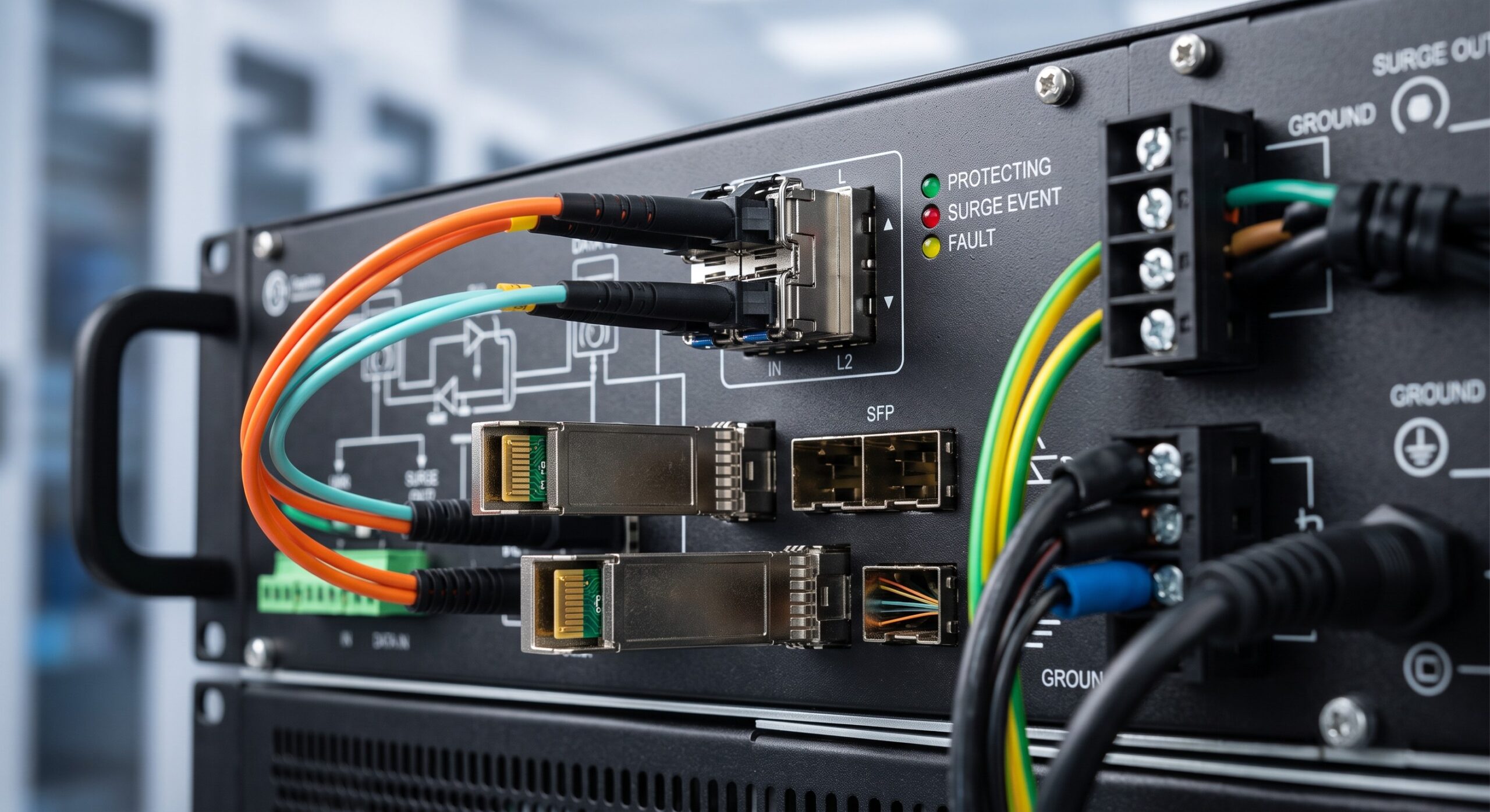
Every external interface, including AC/DC power inputs, Ethernet ports, serial console connections, and GPS antenna feeds, is equipped with dedicated surge protection circuitry. The power supply units incorporate input filtering and surge clamping with a nominal operating voltage range of 100-240 VAC or -48 VDC, providing a surge withstand capability of 6 kV / 3 kA per IEC 61000-4-5. The Ethernet interfaces are protected against both common-mode and differential-mode surges, with a hold-up time that ensures uninterrupted data flow during transient events. Field-replaceable surge protection modules are available for enhanced protection in high-risk installations, such as remote cell sites or rooftop equipment enclosures. These modules can be hot-swapped without interrupting system operation, facilitating maintenance without service disruption. The grounding system is fully redundant, featuring dual grounding lugs and a dedicated ground fault interrupter monitoring circuit that alerts network management systems to any degradation in grounding integrity.
COMPLIANCE & STANDARDS
This hardware protection scheme is designed to meet and exceed the most stringent international standards for surge immunity and safety. The system is fully compliant with IEC 61000-4-5 (Surge Immunity), IEC 61000-4-2 (Electrostatic Discharge), and IEC 61000-4-4 (Electrical Fast Transient/Burst). The equipment carries the CE mark, UL 60950-1/62368-1 certifications, and is verified against GR-1089-CORE for telecom network equipment. The guidelines also align with ITU-T K.20 and K.21 recommendations for overvoltage and overcurrent protection of telecommunication equipment installed in various environmental classes. Additionally, the design adheres to RoHS and REACH environmental directives, ensuring that protective components are free from hazardous substances while maintaining full functional performance.
TECHNICAL SPECIFICATIONS
The technical specifications are detailed below, covering all critical parameters for surge protection integration. These values are validated through type testing on representative hardware configurations and are guaranteed over the full operating temperature range. For exact SKU-level variations, please refer to the ordering and compatibility guide.
| Parameter | Specification |
|---|---|
| Surge Protection Standard Compliance | IEC 61000-4-5 (6 kV / 3 kA), IEC 61000-4-2, IEC 61000-4-4 |
| AC Power Surge Withstand | 6 kV Common Mode, 3 kV Differential Mode |
| DC Power Surge Withstand (-48 VDC) | 6 kV / 3 kA |
| Ethernet Port Surge Protection | 2 kV / 1 kA per IEEE 802.3, Common & Differential Mode |
| Grounding System | Dual Redundant Lugs, Ground Fault Monitoring |
| Operating Temperature Range | -40°C to +65°C |
| MTBF (Surge Protection Subsystem) | 1,500,000 Hours (Bellcore TR-332) |
| Safety Certifications | UL 60950-1, UL 62368-1, CE, GR-1089-CORE |
ORDERING OPTIONS
The surge protection features described in this document are integrated as standard into all chassis variants. For environments requiring enhanced protection, optional external surge protective devices (SPDs) are available as standalone accessories, providing an additional layer of defense for exposed cabling. The optional protection units are available in AC and DC variants, featuring higher surge current ratings (10 kA / 20 kA) and IP67-rated enclosures for outdoor deployment. These accessories include a comprehensive installation kit and are fully compatible with all current-generation line cards and power supplies. Bulk ordering discounts and multi-year support contracts are available for large-scale network deployments. Customers are strongly advised to consult with their regional sales engineer to determine the optimal protection strategy for their specific installation topology and risk profile.
📥 Download Technical Specification
Click the button below to view or download the full official PDF datasheet.

Leave a comment