This chapter describes common causes of the fault that the physical status of GE interfaces cannot Go Up of NetEngine 8100 M14/M8, NetEngine 8000 M14/M14K/M8K/M8/M4 & NetEngine 8000E M14/M8 series, and provides the corresponding troubleshooting flowcharts and examples.
Common Causes
This fault is commonly caused by one of the following:
- Optical modules on the two devices are mismatched.
- The optical fiber is loosely inserted.
- The transmit end and receive end of the optical fiber are reversely connected to the optical modules on the two devices.
Troubleshooting Flowchart
- Perform the local loopback test on the faulty interface to determine whether the fault is caused by a board or subcard failure.
- Check whether the optical fiber and optical modules are working properly.
Troubleshooting flow of GE interface
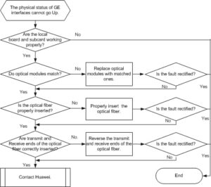
Procedure
- Check that the board and subcard on the local device are working properly.Run the loopback local command on a local interface to enable the loopback function and configure the interface to work in inner loop mode.
After the loopback function is configured, run the display this interface command to view the interface status.
- If the interface is in the Up state, go to Step 2.
- If the interface is in the Down state, the board or subcard has a problem. Contact Huawei to rectify the fault.
- Check that the optical modules on the two interconnected devices match each other.Run the display interface gigabitethernet [ interface-number ] command on the local and remote devices to view information about the optical modules and interface configurations. Note that if the local or remote device is a non-Huawei device, run the command of the corresponding manufacturer to view the information.
Through this information, you can determine:
- Whether optical modules on the local and remote interfaces are matched, whether the optical fiber is correctly connected to the optical modules, and whether the power of the optical modules meets the requirements. If the optical fiber or either of the optical modules does not meet the requirements, replace it.
- Whether the transmit optical power or receive optical power is within the normal range.
If the transmit optical power is not within the normal range, replace the optical module.
If the receive optical power falls below the receiver sensitivity of the optical transceiver, replace the optical module on the remote device or adjust the link.
- Whether the interface configurations on both ends are consistent. If they are inconsistent, adjust them to ensure that configurations are consistent.
- If the connected interfaces are Ethernet optical interfaces or 1000M Ethernet electric interfaces, the working mode of the interfaces must be configured as 1000M full-duplex, with auto-negotiation disabled.
- If the connected interfaces are 10M/100M Ethernet electric interfaces, the working mode of the interfaces is auto-negotiation. In this case, both ends automatically negotiate the duplex mode and working rate.
If the fault persists, go to Step 3.
- Check that the optical modules or the optical fiber is properly inserted.Both the optical module and the optic fiber have card fasteners. If a “click” is heard during the installation of the optic fiber or the optical module, the optic fiber or the optical module has been securely inserted.
If the fault persists, go to Step 4.
- Check that the transmit and receive ends of the optical fiber are correctly inserted into optical modules.Remove the optic fiber, reverse the transmit and receive ends, and reinstall the optical fiber into the optical modules. If the fault is rectified, the two ends of the optic fiber are incorrectly inserted into optical modules.
If the fault persists, restore the optical fiber to the original installation order and go to Step 5.
- Collect the following information and contact Huawei:
- Results of this troubleshooting procedure
- Configuration files, log files, and alarm files of the devices

Leave a comment