
Introduction: The Final Frontier of Fiber Connectivity
In the realm of Fiber-to-the-Home (FTTH) network architecture, the drop cable splicing point represents the final, critical link between the high-speed backbone and the subscriber’s premises. As bandwidth demands escalate, with services requiring multi-gigabit speeds and ultra-low latency, the integrity of this connection is non-negotiable. This definitive guide explores the intricate ecosystem of FTTH drop cable splicing, comparing the dominant technologies, dissecting the operational metrics, and navigating the stringent industry standards that govern modern deployments. Whether you are a systems integrator, a network architect, or a field engineer, understanding the nuances of this process is paramount to maximizing network ROI and ensuring Carrier-Grade Reliability.
The Architecture of FTTH Drop Cables
Understanding the Drop Cable
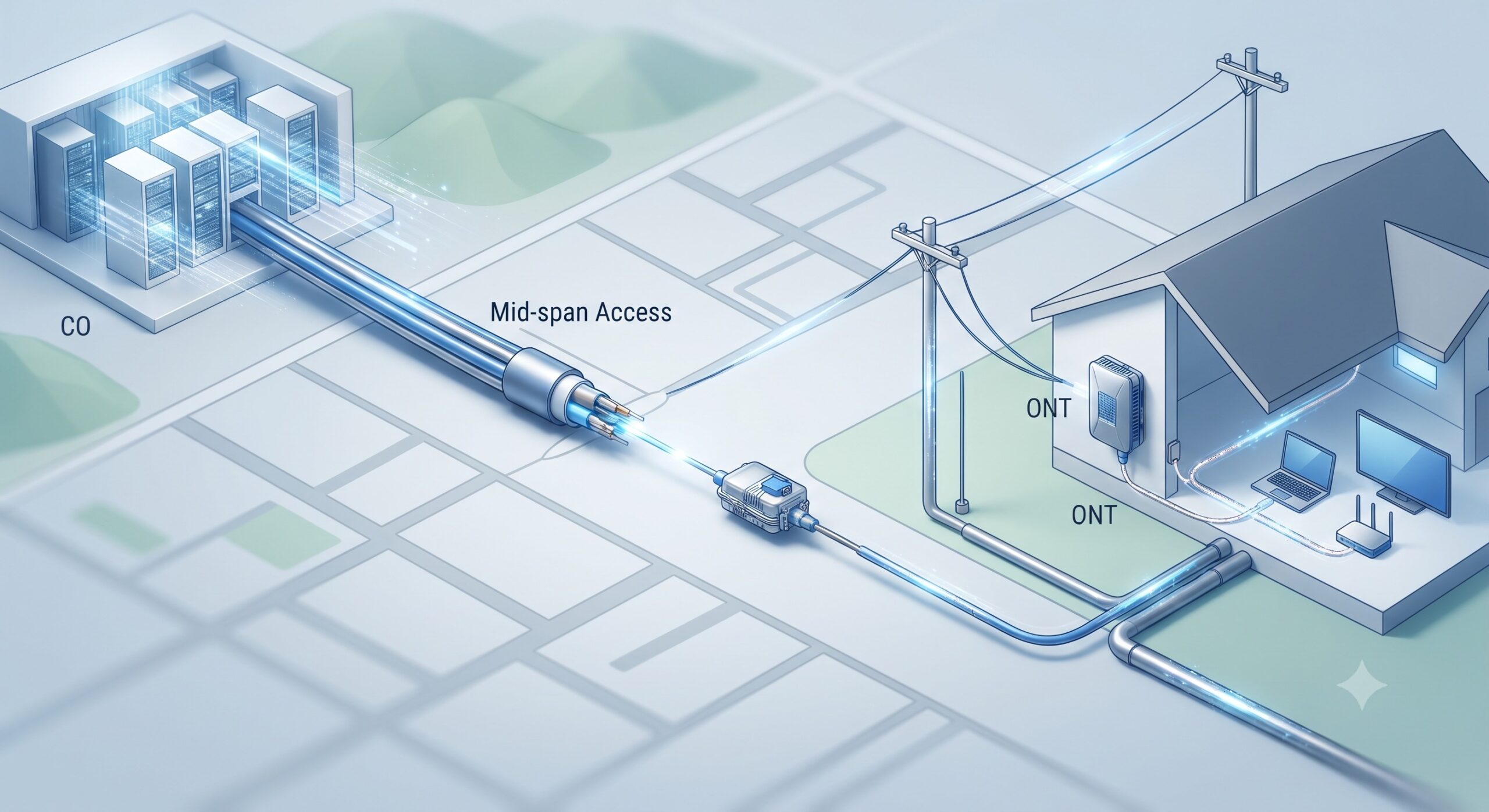
The drop cable forms the final external link, connecting the distribution point at the street to the Optical Network Terminal (ONT) at the customer’s residence . These cables are typically small in diameter and low in fiber count (often a single fiber), designed to be installed aerially, underground, or buried. According to industry standards, a drop cable must possess a minimum pull strength of 1335 Newtons to withstand environmental stresses during installation and its lifecycle . The evolution of fiber technology has introduced bend-insensitive fibers, such as ITU-T G.657.A1/A2, which are often used in drop cables to handle tight bends (e.g., a 15mm radius) without inducing significant signal loss, a critical feature for compact in-home deployments .
Interconnection Strategy: Splice vs. Connector
Before delving into the splicing process, a strategic decision must be made: splice or connector? Both are widely used at the distribution point, but their applications diverge based on network strategy.
- Splices (Permanent Joints): These are ideal for greenfield deployments or dedicated drop cables where no future fiber rearrangement is anticipated. A splice eliminates the possibility of the connection point becoming damaged or dirty, ensuring high signal integrity. However, if a subscriber changes or moves, the splice must be re-done, which can introduce operational complexity .
- Connectors (Reusable Joints): These offer superior network flexibility, allowing for easy adds, drops, and changes. They provide an access point for network testing, which splices cannot offer directly. However, connectors are generally more expensive and are susceptible to contamination and damage if not handled correctly .
Deep Dive: Fusion Splicing in FTTH
Fusion splicing has long been the de facto standard for fiber feeder and distribution networks . The process involves precisely aligning the two bare fiber ends and using an electric arc to melt (fuse) them together permanently. This creates a continuous glass interface with exceptionally low insertion loss and virtually no back reflection.
Technical Specifications and Challenges
While fusion splicing offers superior optical performance, it presents significant challenges when applied to mass FTTH drop deployments, a fact well-documented in industry case studies .
- Capital Expenditure (CapEx): The initial investment is substantial. A handheld fusion splicer can cost upwards of $5,000, with associated tools like cleavers and strippers adding to the cost. For a large deployment, equipping multiple crews becomes a significant financial burden .
- Operational Expenditure (OpEx): Fusion splicers require a local power source (often a battery) and perform optimally in controlled, low-humidity environments. Battery maintenance and potential downtime, coupled with the need for highly trained technicians, increase OpEx. The setup time alone can be several minutes per splice, a significant inefficiency when deploying thousands of drops .
Deep Dive: Mechanical Splicing
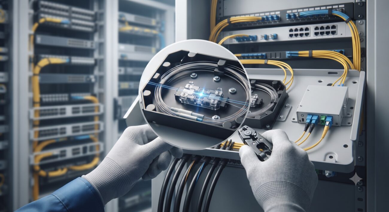
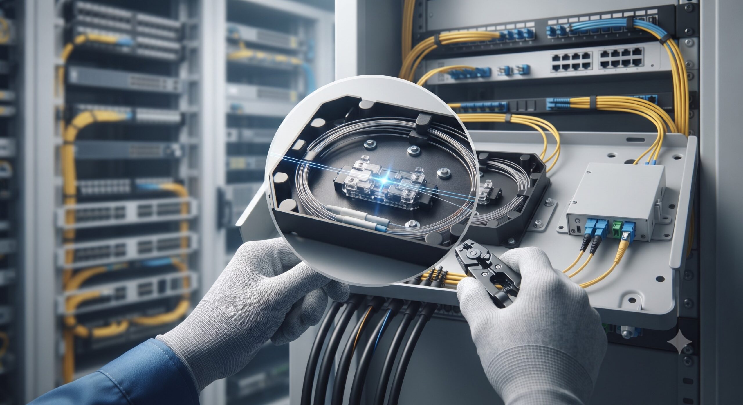
In contrast to fusion splicing, mechanical splicing has emerged as a highly efficient alternative, particularly in Asian markets where mass FTTH deployment is most advanced . A typical mechanical splice consists of a small plastic housing containing a precision aluminum alloy or V-groove element. This element precisely aligns the two prepared fiber ends, which are held in contact and immersed in an index-matching gel that maintains a low-loss optical interface .
Performance Metrics and Efficiency Gains
Data from field deployments reveals the quantifiable advantages of mechanical splicing for drop applications.
- Optical Performance: Modern mechanical splices achieve a median insertion loss of less than 0.1 dB, and many products specify an average of ≤0.2 dB, comparable to low-cost fusion splicing solutions . Return loss typically exceeds 40 dB .
- Speed and Simplicity: The process is quick and does not rely on electrical power. A mechanical splice can be completed in about half the time of a fusion splice. The tools are hand-held, require no work surface, and can be operated from a ladder or at the side of a house .
- Cost and Reliability: The tool set for mechanical splicing, including a cleaver and stripper, can cost less than $1,000, a 90% reduction in initial CapEx compared to fusion equipment . In Japan, which leads the world in FTTH with over 10 million homes connected, service providers reported that mechanical splicing reduced installed costs by 50% and doubled splicing speed, leading to a complete abandonment of fusion splicing for drop applications .
The Splicing Process: Step-by-Step
The mechanical splicing process is straightforward and relies on precision and cleanliness. It involves four primary steps :
- Stripping: Removing the fiber coating from the glass cladding using precision strippers.
- Cleaning: Wiping the bare glass to remove any contaminants that could cause loss.
- Cleaving: Using a precision cleaver to score and break the fiber, creating a perfectly flat, perpendicular end-face. A poor cleave is the most common cause of splice failure.
- Splicing: Inserting the prepared fibers into the mechanical splice housing and activating the splicing tool, which presses the alignment element to clamp and secure the fibers .
Compliance and Standards: The Regulatory Landscape
For any FTTH component to be approved for carrier-grade networks, it must meet rigorous standards defined by bodies like the European Committee for Electrotechnical Standardization (CENELEC) and the International Electrotechnical Commission (IEC). These standards define the performance, mechanical, and environmental requirements to ensure long-term reliability.
| Feature | Fusion Splicing | Mechanical Splicing |
|---|---|---|
| Typical Insertion Loss | ||
| Average Installation Time per Splice | Several minutes (including setup) | ~ 60 seconds |
| Equipment Cost (CapEx) | $5,000+ per crew | |
| Environmental Requirements | Requires power, low humidity, clean surface | Hand-operated, no power, no work surface required |
| Core Technology | Electric arc melts and fuses glass | V-groove alignment with index matching gel |
| Applicable Standards | ITU-T G.652, IEC 60793-2-50 | EN 50411-3-2, EN 50411-3-6 (Mechanical Splices) |
Key standards include the EN 50411 series, which sets the specifications for splice closures and fiber management systems. For instance, EN 50411-2-10 specifies the dimensional, optical, mechanical, and environmental requirements for sealed splice closures in FTTH distribution networks . Similarly, EN 50411-3-2 and EN 50411-3-6 define the performance requirements for single-mode and multi-mode mechanical splices, respectively, covering critical tests such as vibration, impact, torsion, and thermal cycling . A standard-compliant splice must maintain its optical and mechanical integrity under extreme temperatures (from -45°C to +80°C) and environmental stress .
Mid-Span Access and Field Topologies
In FTTH deployment, feeder cables (often G.652.D fibers) run from the central office to a point close to the homes. At this point, a G.657 drop cable is spliced into the feeder. To avoid cutting every fiber in a high-count feeder cable, the Mid-Span Access method is employed . This technique involves opening the cable’s outer jacket at a specific point and accessing only the single fiber destined for the drop, leaving the other fibers untouched . This is a critical skill that minimizes splicing costs and preserves the integrity of the main distribution cable.
Conclusion: The Verdict on FTTH Drop Cable Splicing
Based on industry data and performance analysis, the choice for FTTH drop cable splicing is context-dependent. While fusion splicing remains the gold standard for high-loss-sensitive backbone and long-haul networks, the economics and logistical realities of mass subscriber deployment heavily favor mechanical splicing for the final drop. With its ability to deliver sub-0.1dB insertion loss, robust MTBF data, significant reduction in CapEx, and compliance with key IEC and CENELEC standards, mechanical splicing offers a proven, agile solution for the final frontier of fiber connectivity. For network architects and systems integrators, adopting mechanical splicing for greenfield and large-scale deployments translates directly to maximizing network ROI while ensuring the scalability and reliability demanded by modern broadband ecosystems.

Leave a comment