
The Non-Negotiable Imperative of Network Visibility
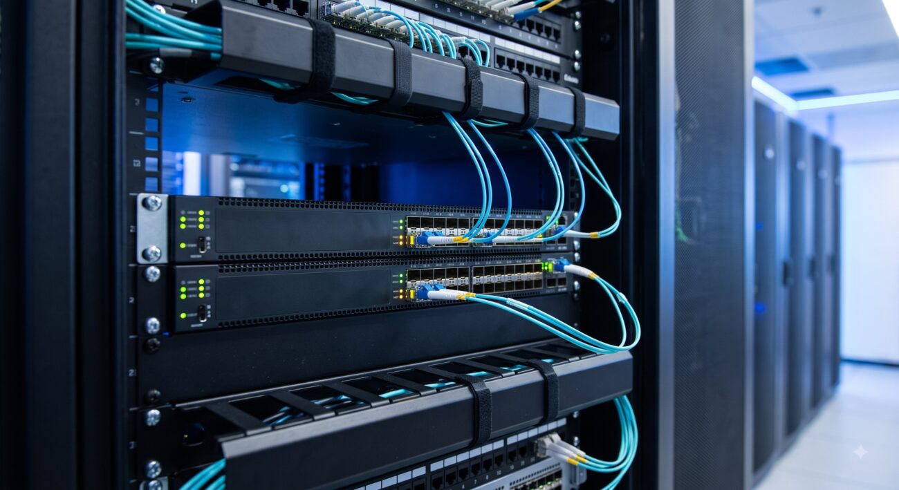
In the modern telecom and enterprise datacenter, network visibility is not a luxury—it is the bedrock of security, performance optimization, and fault resolution. As core routing and switching fabrics scale to support 400G and 800G interfaces, the ability to non-intrusively inspect packet flows becomes paramount. Port Mirroring for Network Monitoring (also known as SPAN or Switched Port Analyzer) remains the most universally deployed technique for delivering traffic to monitoring tools, Intrusion Detection Systems (IDS), and application performance analyzers. This definitive guide dissects the architectural underpinnings, technical specifications, and deployment strategies of port mirroring, providing network architects with the data-driven insights required for high-density, carrier-grade environments .
Core Architecture and Hardware Topology
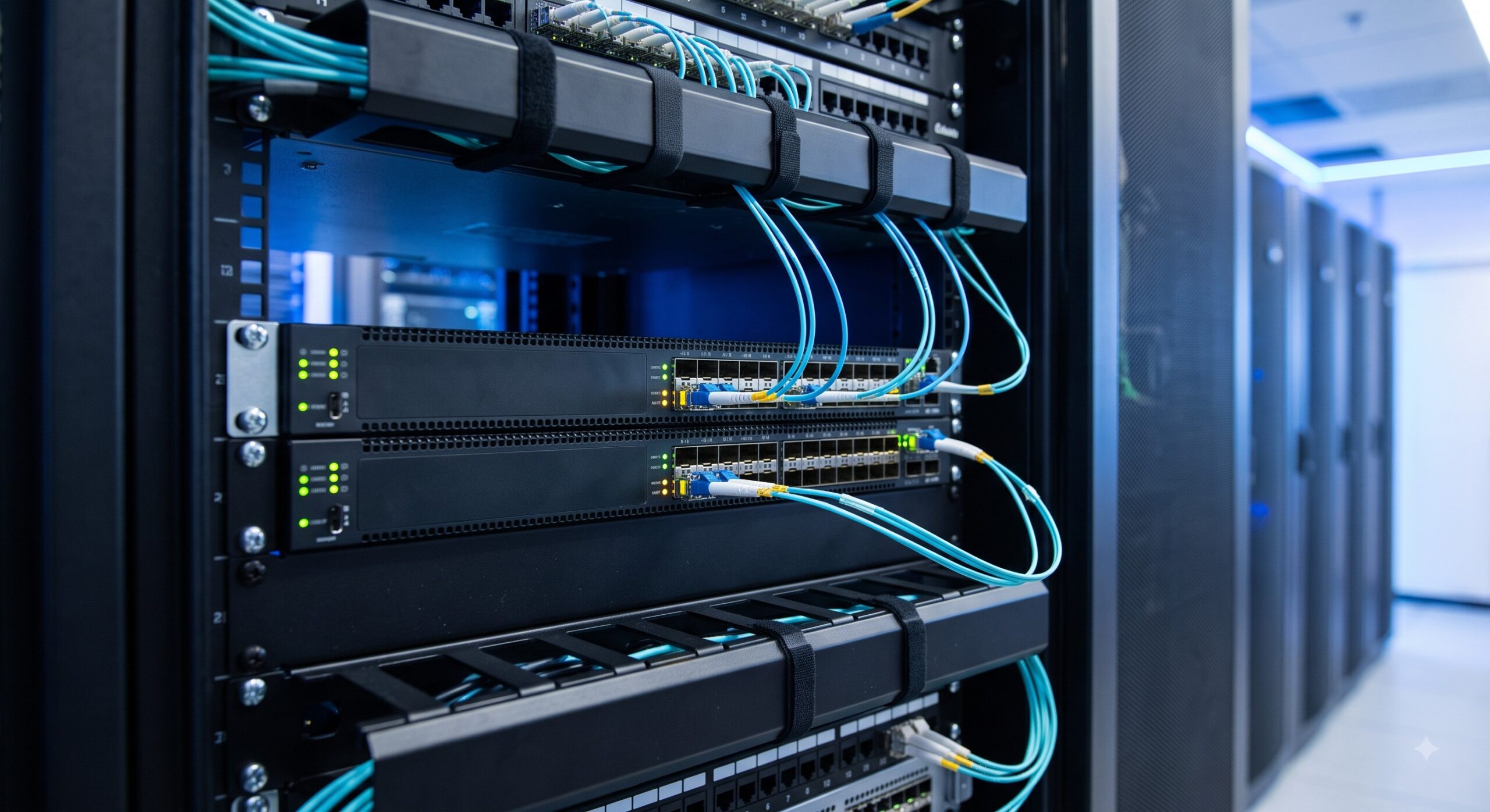
The architecture of port mirroring is defined by the relationship between the mirrored port (source) and the observing port (destination). The ASIC (Application-Specific Integrated Circuit) forwarding engine is responsible for duplicating traffic without impacting the data plane’s forwarding performance.
Local vs. Remote Mirroring: A Topological Decision
Understanding the physical topology is critical for deployment. The two primary architectural models are:
- Local Port Mirroring (SPAN): In this configuration, the observing port is directly connected to the monitoring device on the same switch. The ASIC copies traffic from the source port and forwards it directly out the designated local observing port. This is the most resource-efficient model, offering sub-microsecond latency for mirrored packets .
- Layer 2 Remote Port Mirroring (RSPAN): When the monitoring device resides across a Layer 2 network, traffic must be tunneled. The mirrored traffic is tagged with a dedicated remote mirroring VLAN. Intermediate switches are configured to flood this VLAN to the destination switch, which strips the tag and forwards the traffic to the local observing port. This architecture mandates specific engineering considerations, such as disabling MAC address learning on the mirroring VLAN to prevent forwarding table corruption and ensuring the VLAN is distinct from production traffic .
The ASIC-Level Packet Pipeline
Within the hardware, port mirroring is executed at the hardware level, typically in the packet replication engine of the switching ASIC. The packet enters the ingress pipeline, is classified, and a copy is sent to the egress replication buffer. This process occurs in parallel with standard forwarding, ensuring that the line-rate performance (e.g., 1.44 Tbps on high-density 10G/25G line cards) is maintained. Advanced silicon (e.g., Broadcom Jericho or Tomahawk class) utilizes dedicated mirroring resources to handle the traffic duplication without inducing latency jitter.
| Parameter | Technical Specification |
|---|---|
| ASIC Packet Forwarding | Line-rate performance, typically 1.44 Tbps to 3.2 Tbps (varying by platform) |
| Supported Port Types (Mirrored) | Layer 3 Ethernet, Eth-Trunk, dot1q/QinQ Sub-interfaces |
| Observing Port Restrictions | Only untag/dot1q EVC sub-interfaces; Eth-Trunk supports load-balanced mirroring |
| Bandwidth Management | Committed Access Rate (CAR) for traffic limiting and Packet Slicing (Slice-Size) for header-only mirroring |
| Remote Mirroring VLAN | Requires a dedicated VLAN with MAC address learning disabled to prevent forwarding loops |
Technical Specifications and Performance Metrics Matrix
Selecting the right hardware for port mirroring requires a granular understanding of vendor-specific support and interface limitations.
Supported Interface Types
Not all interfaces can serve as mirrored ports or observing ports. Based on current enterprise configuration guides (e.g., Huawei NetEngine and CloudEngine series), the following matrix applies :
- Layer 3 Ethernet Main Interfaces: Fully supported for both mirroring and observation, including Eth-Trunk (Link Aggregation) interfaces.
- Ethernet Sub-Interfaces: Supported for mirroring (including dot1q and QinQ VLAN tag termination sub-interfaces), but observe-port configuration is restricted—only EVC sub-interfaces with untag or dot1q encapsulation can act as observing ports.
- Eth-Trunk as Observing Port: When an Eth-Trunk is configured as an observing port, mirrored traffic is distributed among member interfaces based on the configured load-balancing algorithm (hash factors). It is critical to note that downstream mirroring starts from the first member interface if Layer 3 header mirroring is enabled .
Operational Limits and Buffer Management
Carrier-grade and datacenter switches are engineered with strict performance boundaries to protect the control plane and forwarding plane:
- Committed Access Rate (CAR): A feature allowing network administrators to apply rate-limiting to mirrored traffic. By configuring CAR (e.g., cir-value and pir-value in Kbps or Mbps), you can prevent a sudden burst of mirrored traffic from overwhelming the CPU or the monitoring tool. This is essential for preventing performance degradation of the switch itself .
- Packet Slicing (Slice-Size): To optimize bandwidth utilization on the observing port, administrators can mirror only the packet headers (e.g., the first 64 or 128 bytes) rather than the entire payload. This dramatically reduces the bandwidth required by the observing port while retaining critical Layer 3/Layer 4 header information for network analysis .
Deployment Topologies and Configuration Best Practices
Effective port mirroring deployment requires a balance between monitoring granularity and resource allocation.
1:N Port Mirroring with Observing Port Groups
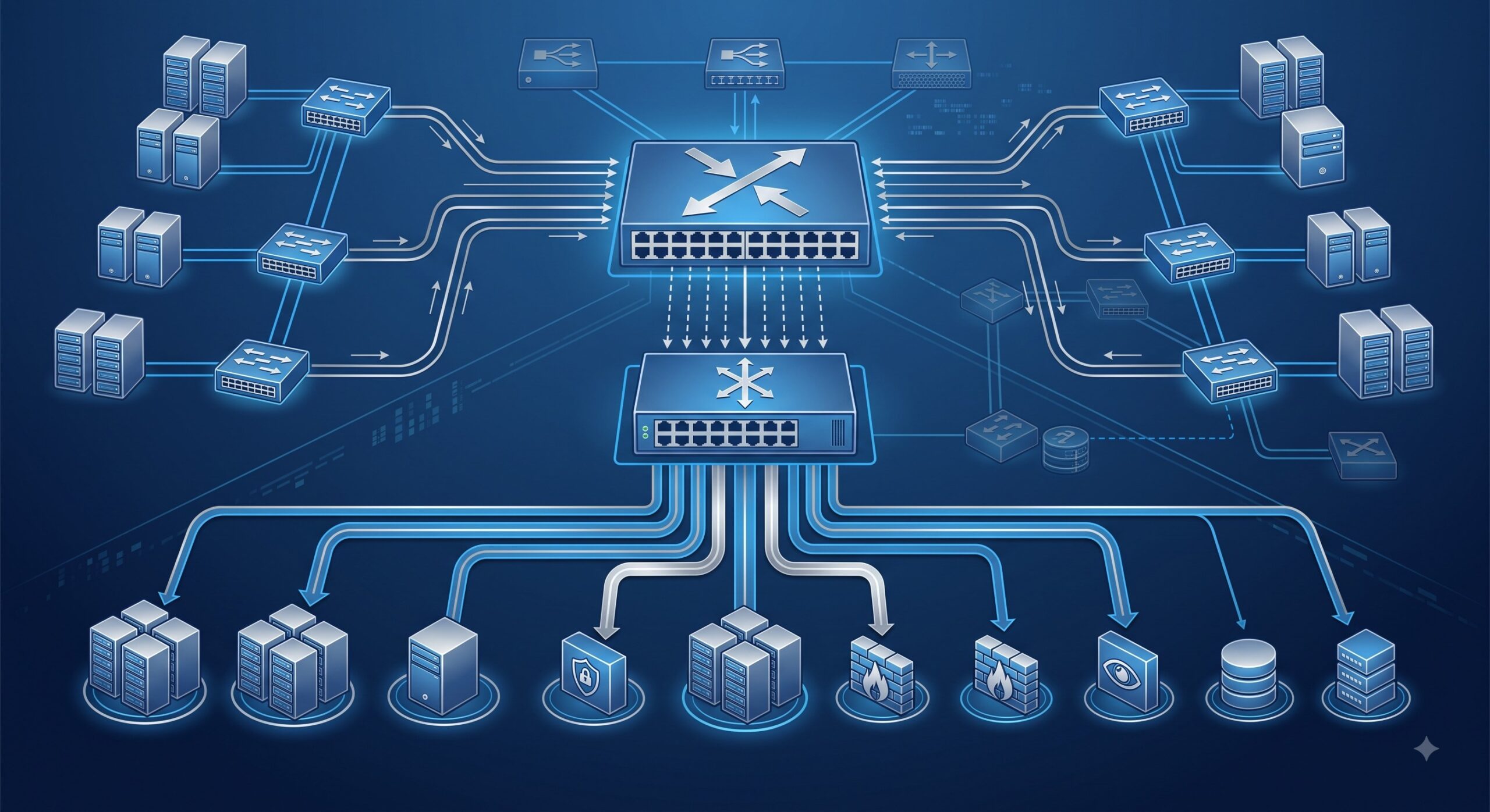
In scenarios requiring multiple analysis tools (e.g., one for security, one for performance, and one for compliance), 1:N mirroring is deployed. By creating an observing port group, traffic from a single source port is replicated to multiple destination ports simultaneously. For example, in a typical R&D department topology, an internet-bound interface is mirrored to a group of local servers. A critical best practice is to disable the forwarding of data packets on observing ports (command: observe-port forwarding disable) to ensure the monitoring device only receives mirrored packets and does not create bridging loops or forward extraneous data into the tool chain .
Traffic Directionality (Inbound vs. Outbound)
The ASIC allows granular control over which traffic is copied :
- Inbound: Copies traffic as it enters the source interface.
- Outbound: Copies traffic as it exits the source interface.
- Both: Copies traffic in both directions (Bi-directional).
Choosing the correct directional parameter is vital for accurate latency analysis. For example, to measure server response time, you would mirror the inbound (request) and outbound (response) traffic on the server-facing interface.
Field Considerations for High-Density Datacenters
In high-density environments, consider the following: Redundancy and Security. Use separate monitoring VLANs to isolate analysis traffic. Ensure the MTU of the mirroring VLAN matches the original traffic to prevent fragmentation. Monitor the utilization of the observing port; if it exceeds 70% consistently, consider implementing packet slicing or load-balancing across multiple observing ports within a group to avoid packet drops.
Conclusion: The Intelligence of the Network
Port Mirroring for Network Monitoring remains a cornerstone of network security and operational intelligence. As we move toward AI-driven networks and 5G core architectures, the integrity of the data fed to our observability stacks depends on the robust, low-latency, and ASIC-level implementation of port mirroring. By adhering to the architectural standards (IEEE 802.1Q for VLANs), leveraging integrated hardware features like CAR and packet slicing, and rigorously following best-practice topologies, telecom engineers can ensure their monitoring infrastructure remains invisible to the production network but invaluable to operations.

Leave a comment