

EXECUTIVE SUMMARY
This document provides a comprehensive technical overview of the primary failure mechanisms affecting optical transceivers in modern telecommunications and data center infrastructure. As the critical physical layer interface between optical networks and electronic switching systems, transceiver reliability is paramount to ensuring network uptime and performance. This datasheet synthesizes field failure analysis data, laboratory stress test results, and industry best practices to delineate the root causes of transceiver degradation and catastrophic failure. Designed for network engineers, procurement specialists, and operations teams, this guide serves as both a diagnostic reference and a preventive maintenance planning tool for maximizing the service life of optical modules.

ARCHITECTURE & CHASSIS DESIGN
The architectural resilience of an optical transceiver is fundamentally linked to its physical and electronic design parameters. Modern pluggable form factors, including SFP, SFP+, QSFP, and QSFP-DD, operate within tightly controlled electrical and thermal envelopes defined by multi-source agreements (MSAs). The primary failure domains are categorized into environmental stressors, electrical overstress, optical interface degradation, and manufacturing variances.
Environmental stressors represent the largest single category of field failures. Temperature extremes and rapid thermal cycling induce mechanical stress at solder joints and within the laser diode package. The laser diode, typically a VCSEL (Vertical-Cavity Surface-Emitting Laser) for multimode applications or a DFB (Distributed Feedback) laser for single-mode applications, exhibits a temperature-dependent wavelength shift and efficiency degradation. Operation outside the specified case temperature range (typically 0°C to 70°C for commercial grade, -40°C to 85°C for industrial grade) accelerates aging mechanisms, leading to a measurable increase in threshold current and a decrease in slope efficiency. Humidity ingress, particularly in non-hermetically sealed modules, can cause corrosion of gold-plated contacts and internal bonding wires, resulting in intermittent connectivity and eventual open circuits.
HARDWARE FEATURES
Electrical overstress (EOS) and electrostatic discharge (ESD) are significant contributors to premature transceiver failure. The high-speed electrical interfaces, operating at data rates up to 800 Gbps per module, are sensitive to voltage transients. Hot-plug events, where a transceiver is inserted or removed from a live host system, can generate inductive spikes that exceed the absolute maximum ratings of the internal driver ICs and the laser diode. The absence of proper ESD protection circuitry, or the failure of such circuitry, compromises the integrity of the transmission lines. Common failure signatures include damaged laser drivers, malfunctioning clock and data recovery (CDR) units, and degraded receiver photodiodes. The physical wear of the electrical edge connector, characterized by reduced insertion cycles, contributes to contact resistance variations that impact signal integrity and power delivery.
COMPLIANCE & STANDARDS
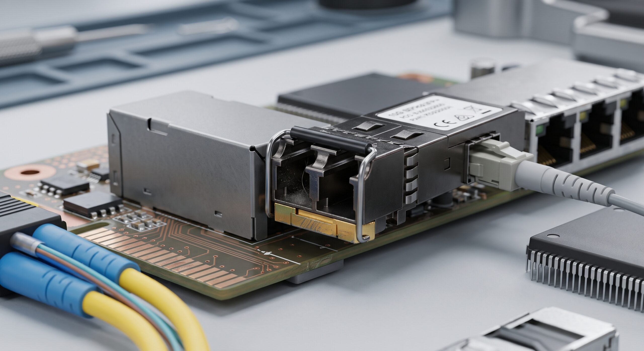
Optical interface degradation is a gradual but inevitable failure mode. Contamination of the ferrule end-face is the most prevalent optical issue. Dust particles, oil residues, and other debris on the connector surface cause scattering and absorption of the optical signal. This results in increased insertion loss and back reflection, leading to bit-error-rate (BER) degradation and, in high-power transceivers, potential thermal damage to the connector interface. Laser safety standards (IEC 60825-1) mandate Class 1 operation, but end-face contamination can create localized hotspots that violate this classification. Furthermore, the physical integrity of the optical fiber within the transceiver’s pigtail or at the receptacle interface is susceptible to micro-bending and macro-bending losses, induced by improper cable management and tight bend radii, which can permanently deform the fiber core.
TECHNICAL SPECIFICATIONS
Manufacturing variances, although statistically less frequent, encompass a range of issues from suboptimal laser chip bonding to faulty soldering of passive components. The alignment of the laser diode to the fiber stub, a process requiring sub-micron precision, is critical for coupling efficiency. Any deviation from the nominal alignment results in lower output power and higher relative intensity noise (RIN). The aging of the laser diode itself, characterized by gradual performance degradation, is accelerated by high operating currents and temperatures. This wear-out mechanism is modeled using Arrhenius equations, enabling Mean Time Between Failures (MTBF) calculations under specific operating conditions. The table below summarizes the key failure modes, their symptomatic indicators, and recommended diagnostic actions.
| Failure Mode | Primary Symptoms | Diagnostic Action | Mitigation Strategy |
|---|---|---|---|
| Thermal Stress / Laser Aging | Increased bias current, reduced output power, wavelength drift | Monitor DDM; check case temperature logs | Ensure proper airflow; use industrial-grade modules for extreme environments |
| Optical End-Face Contamination | High insertion loss, elevated BER, intermittent link loss | Inspect with optical microscope; analyze return loss | Implement stringent cleaning protocols; use dust caps |
| Electrostatic Discharge (ESD) | Catastrophic laser failure, non-functional module, TX/RX fault | Verify ESD protection circuitry; inspect for physical damage | Use ESD-safe handling procedures; wrist straps and grounded workstations |
| Hot-Plug Electrical Overstress | Driver IC burnout, CDR malfunction, intermittent CRC errors | Check voltage transient logs; swap with known-good module | Use host equipment with advanced surge protection; controlled insertion |
| Fiber Bending & Mechanical Stress | Increased attenuation, erratic link performance | Test with OTDR; inspect fiber routing path | Adhere to minimum bend radius; use proper cable management guides |
ORDERING OPTIONS
Proactive transceiver lifecycle management necessitates a thorough understanding of operational thresholds. Operators are advised to implement Digital Diagnostic Monitoring (DDM) to track real-time parameters such as temperature, supply voltage, laser bias current, and optical output power. Anomalies in these parameters serve as early warnings of impending failure. Maintenance protocols should include routine end-face cleaning using industry-standard tools and inspection with an optical microscope to verify cleanliness and surface integrity. Environmental controls within data centers, particularly temperature and humidity regulation, are essential to mitigate the effects of thermal stress. The selection of transceivers should be aligned with the specific grade (commercial, industrial, or extended) required by the deployment environment, a factor that directly influences the total cost of ownership and network reliability.
📥 Download Technical Specification
Click the button below to view or download the full official PDF datasheet.

Leave a comment