
EXECUTIVE SUMMARY
The Huawei OptiX OSN 9800 U64 represents the pinnacle of high-capacity optical transport networking, engineered to meet the insatiable bandwidth demands of super-backbone, backbone, and metro core networks. As a flagship member of the OSN 9800 U series, the U64 subrack is a frame-and-cabinet integrated platform designed for 100G, 200G, and 400G transmission, with a clear evolution path beyond 1T per slot. This document provides a definitive technical overview of the U64 subrack’s physical architecture, slot allocation strategy, and critical cable routing methodologies. It serves as an authoritative reference for network planners, systems engineers, and installation personnel tasked with deploying this carrier-grade infrastructure. The U64 distinguishes itself through its massive 64-slot capacity, intelligent power distribution system, and a meticulously organized fiber management scheme that ensures operational efficiency and long-term reliability in high-density environments.
ARCHITECTURE & CHASSIS DESIGN
The OptiX OSN 9800 U64 is a dual-face subrack design, meaning it utilizes both the front and rear of the chassis for board installation and cable access. This architecture maximizes capacity within a standard footprint. The subrack is integrated into a cabinet with dimensions of 2200 mm (H) x 600 mm (W) x 600 mm (D), providing a robust, pre-cabled solution for rapid deployment . The physical layout is logically partitioned into distinct functional zones: the Service Board Areas, the System Control and Cross-Connect Area, the Power and Interface Area, the Fan Areas, and the critical Fiber Routing Areas.
The Service Board Areas provide a total of 64 slots for universal service boards. These are split between the front and rear of the subrack. The front service area accommodates 32 boards across slots IU1 through IU32, while the rear service area accommodates another 32 boards in slots IU33 through IU64 . This dual-sided access allows for a high density of line cards while maintaining a manageable depth for cabling and maintenance. The System Control and Cross-Connect Area houses the intelligent control units and the high-capacity switching fabric. The U64 employs a 1+1 backup configuration for the System Control Boards (CTU) in slots IU70 and IU78. The Cross-Connect Boards (XCS) are installed in slots IU71-IU77 (front) and IU79-IU85 (rear), forming a dynamic resource pool that provides non-blocking cross-connections for the entire system .
HARDWARE FEATURES AND POWER ARCHITECTURE
A hallmark of the U64 design is its intelligent and flexible power supply system. The subrack utilizes Power Interface Units (PIUs) located in the dedicated power and interface area. The power distribution is not a simple bus; it is a zone-based system where specific PIUs feed specific groups of slots. This design enhances availability and allows for incremental power provisioning. For instance, PIU boards IU100 and IU121 (active/standby) supply power to the system control, cross-connect, and front fan areas. Similarly, IU106 and IU115 handle the rear control and fan areas . The service board slots are powered by dedicated groups of PIUs. The system supports an N+N or active/standby power backup scheme depending on the load. For the high-density service slots (e.g., IU17-IU32), four PIU boards (IU101, IU103, IU118, IU120) are available. When the power consumption of the area is below 2400 W, a single active PIU with a standby can supply the load. When power demands exceed 2400 W, the system can utilize two PIUs in a load-sharing mode to ensure stable operation . This granular control over power delivery is a key enabler for the U64’s high-density, high-reliability profile.
FIBER ROUTING AND CABLE MANAGEMENT
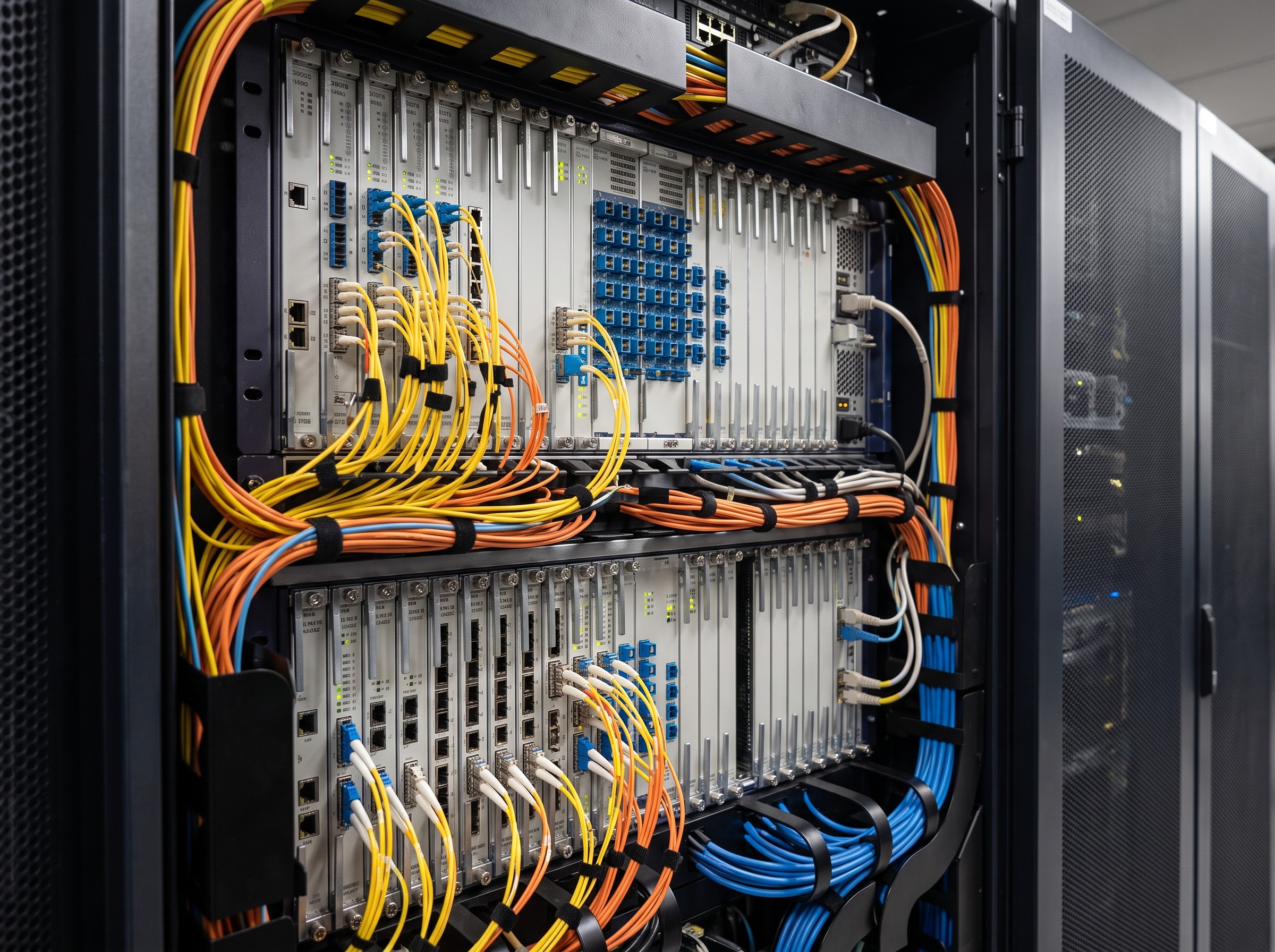
Effective cable routing is paramount in a 64-slot optical transport system to prevent congestion, ensure bend radius compliance, and facilitate maintenance. The U64 incorporates dedicated Fiber Routing Areas (fiber troughs) on both the front and rear sides of the subrack. These troughs are located on the left and right flanks of the equipment, providing a structured path for patch cords from the board faceplates to the cabinet sidewalls . The routing philosophy is based on a top-and-bottom approach. Fiber jumpers from the service boards are guided horizontally into the vertical fiber troughs. These troughs then channel the fibers vertically towards the top or bottom of the rack, where they can be routed to the Optical Distribution Frame (ODF) or interconnected with other subracks.
For the Network Management (NM) and inter-subrack communication cables, specific routing constraints must be observed. The CTU boards, which handle control plane and management traffic, have dedicated cable saddle clamps mounted on the subrack sides adjacent to the CTU slots. NM cables must be routed through these clamps and then into the fiber troughs, ensuring they are physically separated from high-density service fibers to prevent interference and simplify troubleshooting . The physical design of the board ejector levers also aids in cable management: boards in slots IU1-IU16 and IU33-IU48 have levers on the right, while others have levers on the left, creating a natural asymmetry that helps differentiate cable bundles during installation and maintenance .
COMPLIANCE & STANDARDS
The OptiX OSN 9800 U64 is designed to meet stringent international standards for telecommunications equipment. It complies with ITU-T recommendations for optical transport networking (G.709, G.798) and supports a wide range of service types including SDH/SONET, Ethernet, OTN, and Storage Area Network (SAN) protocols. The platform adheres to ETSI standards for equipment practice and is designed for deployment in ETSI 300/600 compliant cabinets, though the U64 is typically supplied as an integrated cabinet solution . Environmental compliance includes operation within standard carrier-grade temperature and humidity ranges, with redundant fan tray assemblies providing forced-air cooling across the front and rear board areas. The system supports synchronization according to IEEE 1588v2 and Synchronous Ethernet, ensuring it can serve as a reliable timing source for modern mobile and fixed networks .
TECHNICAL SPECIFICATIONS
The following table summarizes the key physical, electrical, and capacity parameters of the Huawei OptiX OSN 9800 U64 subrack.
| Parameter | Specification |
|---|---|
| Form Factor | Frame-and-Cabinet Integrated Subrack (Dual-Face) |
| Dimensions (Integrated Cabinet) | 2200 mm (H) x 600 mm (W) x 600 mm (D) |
| Service Board Slots | 64 Total (32 Front: IU1-IU32, 32 Rear: IU33-IU64) |
| System Control Slots | 2 (1+1 Backup: IU70, IU78) |
| Cross-Connect Slots | 14 Total (Front: IU71-IU77, Rear: IU79-IU85) |
| Switching Capacity (ODUk) | 25.6 Tbit/s (Standard U64) |
| Switching Capacity (Packet) | 12.8 Tbit/s |
| Power Supply | DC -48V/-60V; Zone-based PIU distribution with Active/Standby and Load-Sharing modes |
| Redundancy | Control 1+1, Cross-Connect M:N Pool, Fan Redundancy, Power Redundancy |
| Fiber Routing | Dedicated Front and Rear Fiber Troughs (Left/Right Sides) |
| Cooling | Redundant Fan Tray Assemblies (Front: IU90-93, Rear: IU94-97) |
ORDERING OPTIONS AND DEPLOYMENT CONSIDERATIONS
Procurement of the OSN 9800 U64 involves selecting the appropriate subrack configuration and associated hardware. The integrated cabinet model simplifies ordering, as the subrack, fans, and basic cabling are pre-assembled. Key ordering considerations include the quantity and type of Cross-Connect Boards (XCS) required for the desired switching capacity (up to 25.6 Tbit/s ODUk for the standard U64, or higher with enhanced cross-connect boards), the specific Service Boards (line cards and tributary cards) for the target application, and the number of Power Interface Units needed based on the calculated power budget and redundancy requirements . When planning cable routing, it is essential to pre-order sufficient fiber patch cords of the correct length and connector type (e.g., LC, SC) and to plan for the vertical cable management infrastructure within the equipment room. The dual-face design means that installation and maintenance workflows must account for access to both the front and rear of the cabinet, though the structured fiber troughs are designed to minimize the need for frequent rear access once initial cabling is complete.
📥 Download Technical Specification
Click the button below to view or download the full official PDF datasheet.
Leave a comment