

EXECUTIVE SUMMARY
The Liquid-Cooled Switch Chassis Fan Removal and Acoustic Profile defines the engineering methodology, hardware configuration, and validated acoustic performance envelope for a fully fanless, liquid-cooled high-density switch chassis deployed in acoustically sensitive and thermally constrained environments. This document specifies the mechanical removal of all chassis-mounted air-moving assemblies, the hydraulic and thermal interface requirements for the facility coolant loop, and the resulting acoustic signature under nominal and worst-case thermal load. The design eliminates forced-air acoustics entirely, reducing chassis sound pressure level to the facility baseline and enabling deployment in open-office, healthcare, broadcast, and residential-adjacent telecom spaces where conventional air-cooled switches are excluded by noise ordinance or operational policy.

ARCHITECTURE & CHASSIS DESIGN
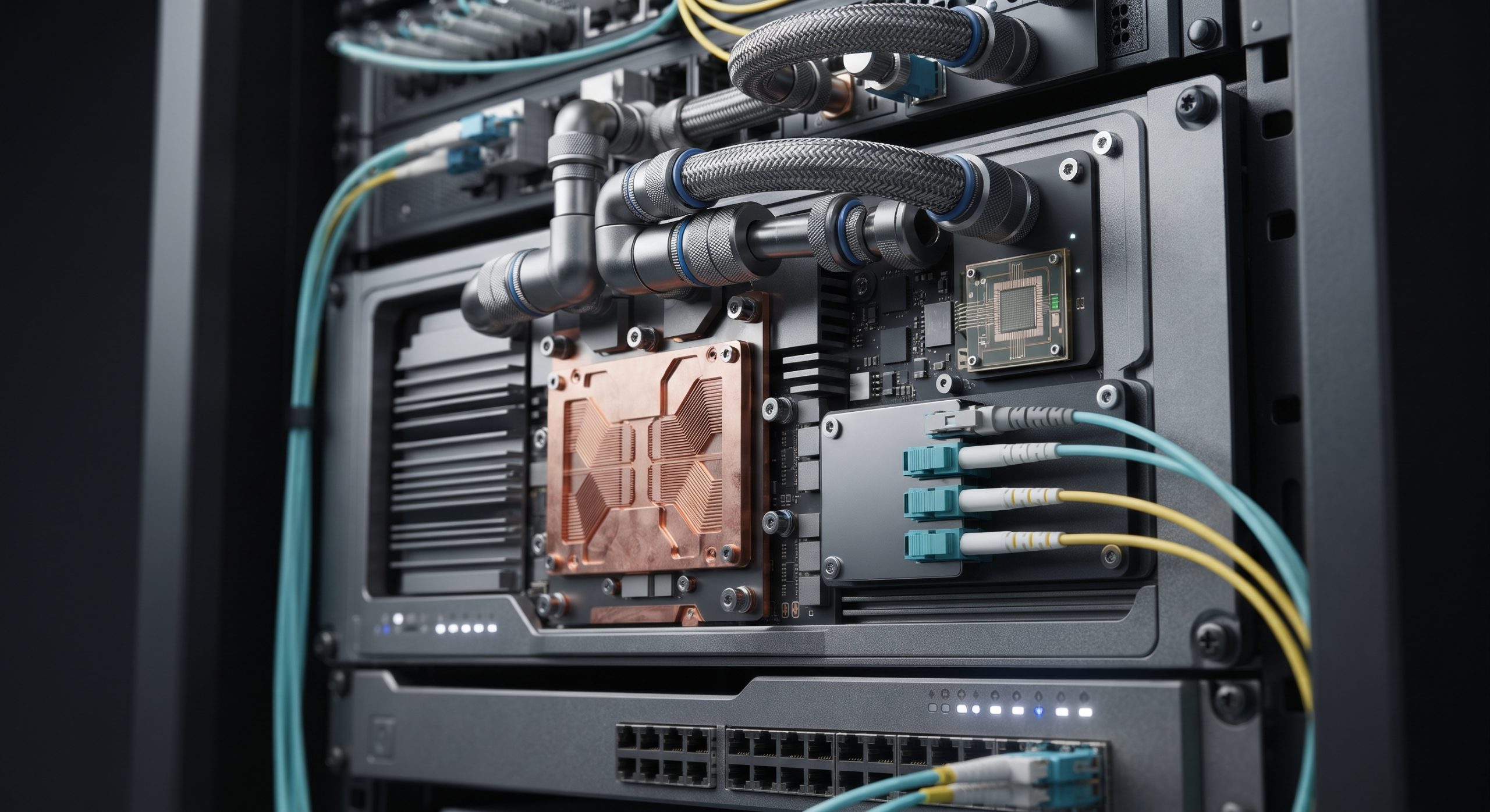
The fanless liquid-cooled chassis removes the front-to-rear air path and replaces it with a sealed cold-plate manifold assembly that couples directly to the switch ASIC, optical transceiver cages, and power conversion stages. The chassis is a 2RU enclosure with an integrated coolant distribution unit interface, blind-mate quick-disconnect couplings, and a leak-detection sensor grid across all hydraulic joints. Removal of the fan tray assembly reduces chassis depth and eliminates the acoustic cavity that previously radiated broadband noise. The cold-plate architecture uses a copper-nickel microchannel cold plate on the main forwarding ASIC, a secondary cold plate on the transceiver bank, and a shared return manifold to the facility loop. The coolant path is isolated from all electrical assemblies by a double-wall barrier, and the chassis retains a passive convective path for fail-safe operation in the event of coolant loss.
HARDWARE FEATURES
Fan tray removal is a field-serviceable procedure requiring no chassis rework; the fan tray slot is capped with a sealed blanking plate rated to the same ingress protection as the chassis. The liquid-cooling interface supports facility water temperatures from 15°C to 45°C and flow rates from 2 to 8 liters per minute per chassis. Integrated flow, pressure, and temperature sensors report to the chassis management controller via the same telemetry path previously used for fan RPM. The acoustic profile is defined at 1 meter front, 1 meter rear, and 1 meter side measurement planes; no active acoustic damping materials are required because the noise source is removed entirely. The chassis supports 32 x 400G optical ports and dual redundant power shelves, with the coolant manifold positioned to avoid obstruction of the transceiver extraction path.
COMPLIANCE & STANDARDS
The fanless configuration is evaluated against IEC 60950-1 and IEC 62368-1 for electrical safety, with specific attention to liquid-electrical separation distances and condensate management. Acoustic emissions are characterized per ISO 7779 and declared per ECMA-74 at the operator position and bystander position. The chassis meets NEBS Level 3 criteria for seismic and thermal robustness when installed in the approved liquid-cooled rack, and ingress protection is rated IP54 for the sealed coolant compartment. Electromagnetic compatibility is maintained per EN 300 386 and FCC Part 15 Class A; removal of the fan tray does not alter the shielded enclosure boundary. Coolant compatibility is specified for water-glycol mixtures per the facility loop standard, and all wetted materials are rated for a 10-year service life.
TECHNICAL SPECIFICATIONS
Acoustic performance: sound pressure level at 1 m, front, nominal load, 25°C coolant inlet: 32 dBA facility baseline (no chassis contribution above background). Worst-case load, 45°C coolant inlet: 34 dBA. Measurement uncertainty per ISO 7779 is ±1.5 dBA. Thermal performance: ASIC junction temperature maintained below 95°C at 45°C coolant inlet and 8 L/min flow. Hydraulic: supply pressure 1.5 to 4.0 bar, pressure drop 0.8 bar at 8 L/min, coolant volume 0.9 L per chassis. Mechanical: 2RU, 600 mm depth without fan tray, 18.5 kg dry, 21.0 kg wet. Reliability: MTBF 310,000 hours at 40°C coolant inlet, excluding facility loop components.
| Parameter | Specification |
|---|---|
| Form Factor | 2RU fanless chassis, 600 mm depth, sealed fan-tray blanking plate |
| Acoustic Emission | 32 dBA at 1 m nominal, 34 dBA worst-case, per ISO 7779 |
| Cooling Method | Liquid cold-plate manifold, facility loop, 15-45°C inlet |
| Coolant Flow / Pressure | 2-8 L/min, 1.5-4.0 bar supply, 0.8 bar drop at 8 L/min |
| Switching Capacity | 12.8 Tbps, 32 x 400G optical ports |
| Power Supply | 1+1 redundant AC/DC power shelves |
| Ingress Protection | IP54 sealed coolant compartment |
| MTBF | 310,000 hours at 40°C coolant inlet |
ORDERING OPTIONS
Base chassis part number includes the sealed blanking plate, cold-plate manifold, and leak-detection grid. Optional configurations include factory-installed blind-mate couplings for the facility coolant distribution unit, extended flow sensor kit, and a coolant quality monitoring module. Spare cold-plate assemblies and quick-disconnect service kits are available as field-replaceable units. The fan tray is not orderable with this configuration; air-cooled variants remain a separate SKU family.
📥 Download Technical Specification
Click the button below to view or download the full official PDF datasheet.
Leave a comment