
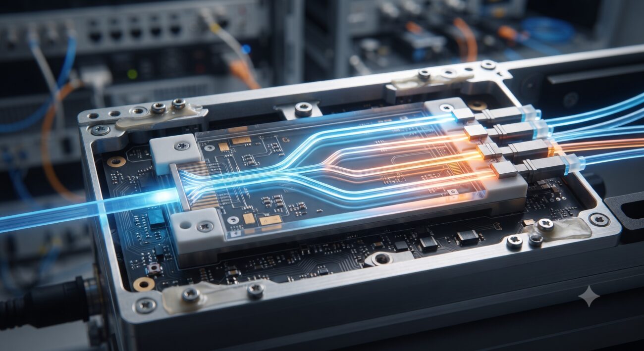
Introduction: The Critical Role of Attenuation in PON Architecture
In the realm of passive optical networks (PON), the optical splitter is the quintessential enabler of Fiber-to-the-Home (FTTH) and enterprise connectivity. However, it introduces a fundamental network design constraint: optical splitter attenuation. This loss, often the largest power penalty in a PON system , dictates the reach, split ratio, and overall feasibility of a deployment. For the elite network architect, understanding the nuances of insertion loss, uniformity, and environmental stability is not optional—it is the bedrock of reliable, high-performance network engineering. This technical deep-dive explores the attenuation characteristics of modern splitters, dissecting the physics, specifications, and real-world implications.
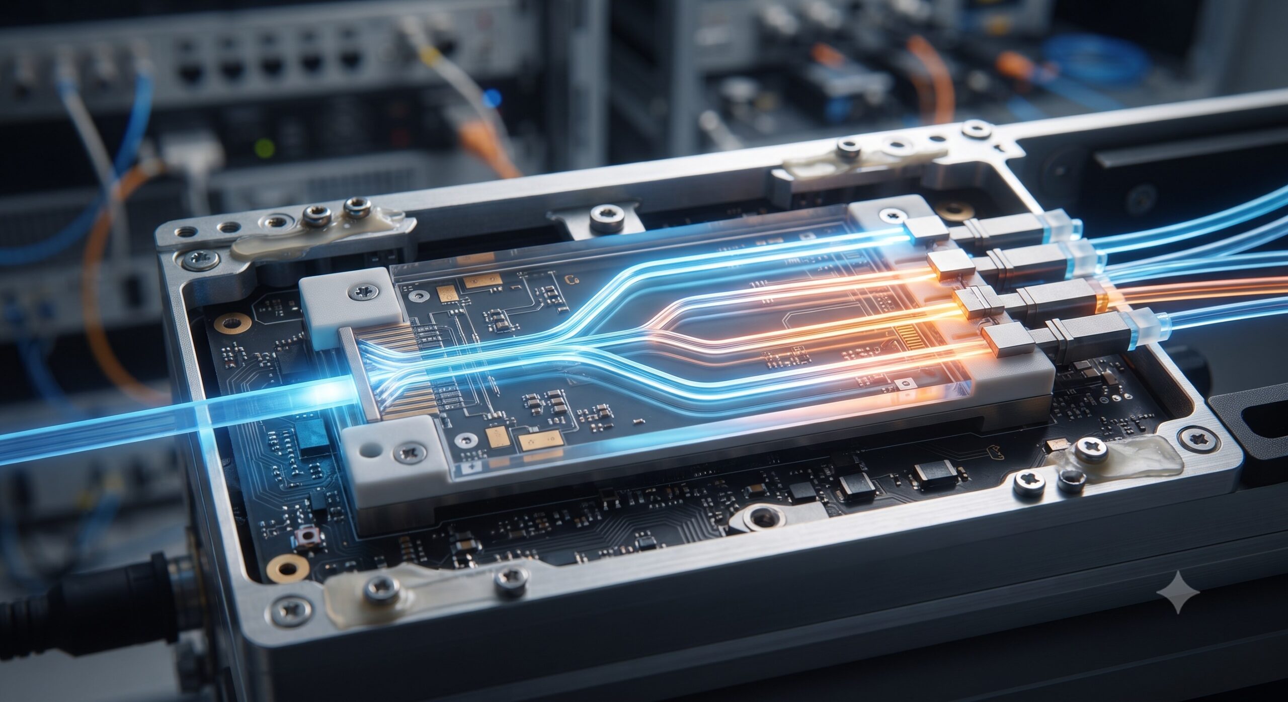
Core Architecture and Hardware Topology
Understanding attenuation begins with the physical layer. Optical splitters are categorized into two primary architectures: Fused Biconical Taper (FBT) and Planar Lightwave Circuit (PLC) .
- FBT Splitters: Fabricated by fusing and tapering two or more optical fibers together. They are cost-effective for low-port-count configurations (e.g., 1×2, 1×4) but exhibit higher wavelength dependence and less uniform splitting ratios compared to their PLC counterparts .
- PLC Splitters: Manufactured using semiconductor photolithography to create waveguides on a silica glass substrate. This process enables precise, even splitting over the entire single-mode operating window (1260–1650 nm), making them the industry standard for high-density, high-uniformity applications such as GPON and XGS-PON .
The choice of splitter technology directly influences the attenuation profile and the adherence to standards such as Telcordia GR-1209-CORE and GR-1221-CORE, which mandate strict performance criteria for reliability and insertion loss .
Logic Layer Deep Dive: Characterizing Attenuation
Optical splitter attenuation is a composite metric, primarily driven by two key parameters: Insertion Loss and Splitter Uniformity.
The Physics of Splitting Loss
The theoretical minimum loss for an ideal 1xN splitter is 3.01 dB for each doubling of the split ratio, mathematically expressed as 3.01 log2(N) dB. However, real-world devices incur additional Excess Loss due to scattering, absorption, and waveguide imperfections within the splitter itself . The GR-1209 standard provides a practical approximation for maximum insertion loss: 0.8 + 3.4 log2N .
| Split Ratio | Typical Insertion Loss (dB) | Max Insertion Loss (dB) | Uniformity (dB) | PDL (dB) |
|---|---|---|---|---|
| 1×2 | ≤3.8 | 4.0 | ≤0.5 | ≤0.2 |
| 1×4 | ≤7.0 | 7.4 | ≤0.6 | ≤0.2 |
| 1×8 | ≤10.2 | 10.8 | ≤0.8 | ≤0.3 |
| 1×16 | ≤13.5 | 14.3 | ≤1.0 | ≤0.3 |
| 1×32 | ≤16.5 | 17.4 | ≤1.5 | ≤0.3 |
Operational Parameters and Environmental Effects
Beyond raw insertion loss, a high-performance splitter must maintain its characteristics across a wide range of environmental conditions. This is where metrics like Polarization-Dependent Loss (PDL), Wavelength-Dependent Loss (WDL), and Temperature Stability come into play. As per industry specifications , a carrier-grade splitter operating from -40°C to +85°C must exhibit:
- Polarization-Dependent Loss (PDL): Typically ≤0.2 dB for low port counts, increasing slightly to ≤0.4 dB for high-density 1×64 configurations.
- Wavelength-Dependent Loss (WDL): Maintaining uniformity across the entire 1260–1650 nm band, usually within ±0.3 to 0.55 dB.
- Return Loss and Directivity: High-grade splitters guarantee a Return Loss ≥55 dB and Directivity ≥55 dB, minimizing signal reflections that can degrade transmitter performance .
Benchmark vs. Legacy: Quantifying Operational Gains
Modern PLC splitters represent a significant leap over legacy FBT devices. In a 1×32 configuration, for instance, a premium-grade PLC splitter guarantees a maximum insertion loss of ≤17.5 dB, whereas a standard FBT splitter might exhibit a less uniform power distribution with a higher peak loss of up to 18.0 dB . This improved uniformity (≤1.5 dB vs. up to 1.8 dB for legacy) ensures that the power budget is not skewed towards a specific output port, simplifying network planning and reducing the need for optical amplifiers (EDFAs) or higher-power transceivers, which cost upwards of $1,500+ per node . In the context of a 10 Gbps link, maintaining strict control over splitter attenuation is the difference between a successful deployment and a failed budget.
ISP Case Study: Managing Attenuation in a 10G-PON Fronthaul
Consider a regional ISP migrating from GPON to 10G-PON (XGS-PON). The downstream power budget for XGS-PON is significantly tighter. By deploying premium-grade 1×8 PLC splitters with a maximum insertion loss of ≤10.5 dB and low PDL (

Conclusion: The Attenuation Imperative
Optical splitter attenuation is the single most critical passive factor in PON network design. A deep understanding of the specifications—beyond just the nominal insertion loss—is essential. As network architects push for higher split ratios (e.g., 1×64, 1×128) and higher data rates (50G-PON), the demand for ultra-low-loss, thermally stable PLC splitters compliant with the latest ITU-T and IEEE standards becomes paramount. Optimizing for attenuation isn’t just about loss; it’s about maximizing the Total Cost of Ownership (TCO) by enabling longer reaches, higher split counts, and greater network reliability.

Leave a comment