
Identifying Containment Airflow Bottlenecks in High-Density Telecom Environments
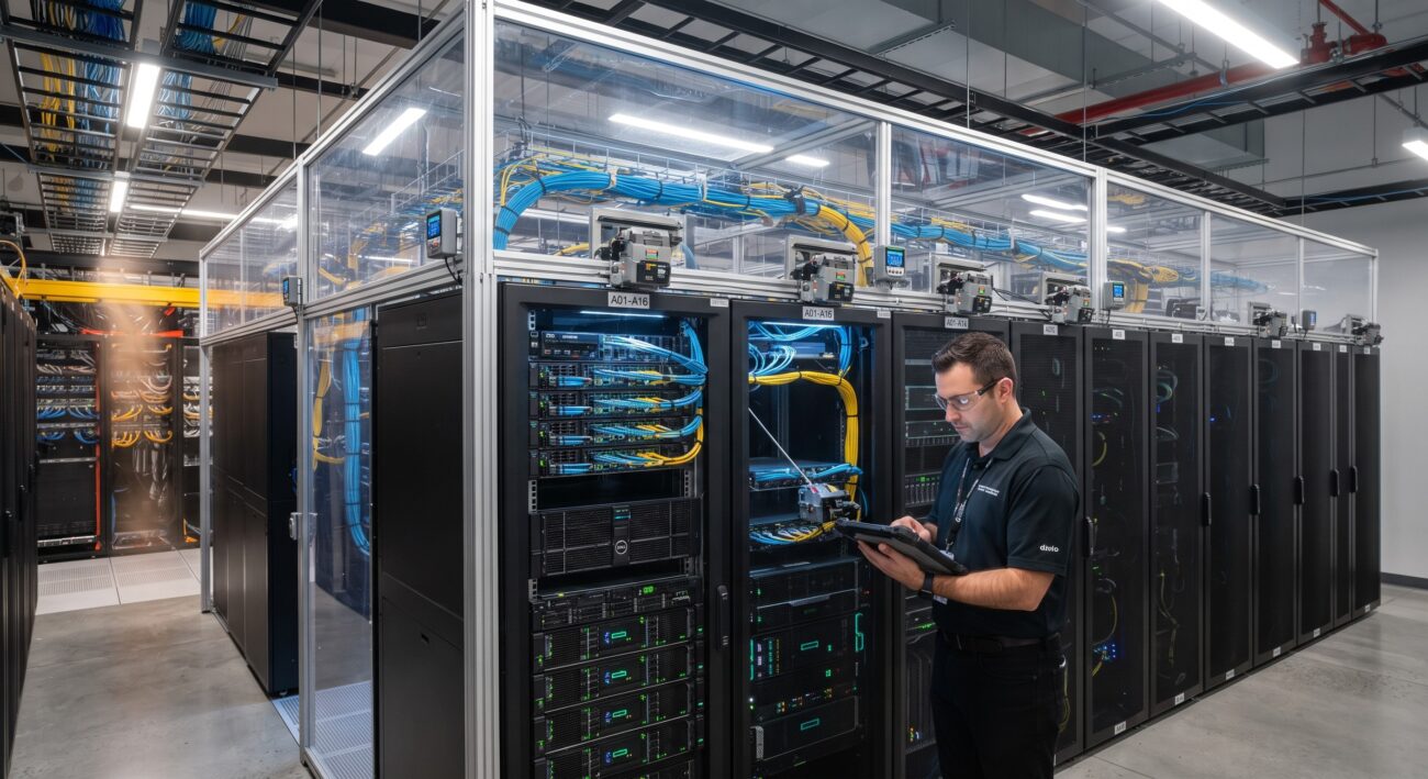
The migration from legacy telecom central offices to high-density edge compute facilities has exposed a critical operational paradox: physical aisle containment, while essential for segregating hot and cold fluid streams, frequently underperforms due to static airflow provisioning. In a typical contained hot aisle (HAC) or cold aisle (CAC) deployment, the cooling infrastructure is often configured for peak design load, yet actual IT equipment airflow demand fluctuates dynamically with workload utilization and server fan modulation. This mismatch creates two distinct failure modes: bypass airflow (conditioned air escaping without cooling IT equipment) and recirculation (hot exhaust air entraining back into the cold intake). Field measurements from a legacy facility demonstrate the severity of the issue—a Return Temperature Index (RTI) of 44% indicated that the cooling system was delivering 2.3 times more air than the IT equipment required, resulting in wasted fan energy and stranded cooling capacity .
For telecom hardware operators managing carrier-grade infrastructure, the consequence is not merely energy inefficiency but a direct threat to MTBF (Mean Time Between Failures). Servers operating outside ASHRAE recommended intake envelopes experience accelerated component degradation, with every 10°C rise above 25°C potentially halving semiconductor reliability. The solution lies not in adding more cooling capacity, but in dynamic air-balance tuning—the active, sensor-driven modulation of dampers, fan arrays, and containment pressure boundaries to match real-time IT demand.
Solving Latency and Thermal Runaway via Active Pressure Architecture
The Physics of Differential Pressure Control
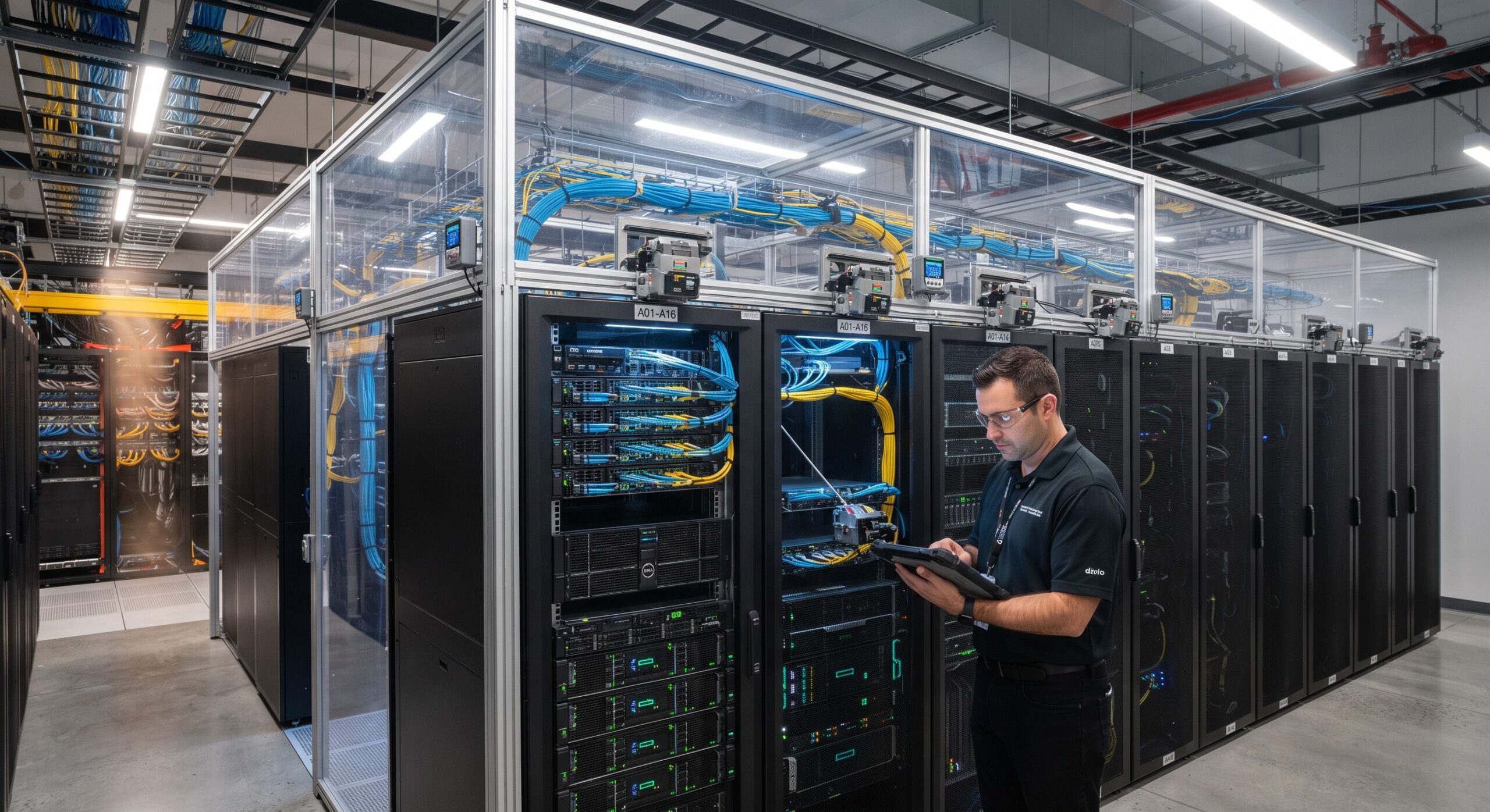
The fundamental mechanism of dynamic balancing relies on maintaining a near-neutral or slightly positive pressure within the contained aisle relative to the surrounding room. In a ceiling-ducted hot aisle containment system, each aisle pod is equipped with a motorized damper and a differential pressure sensor. When server fan speeds increase due to rising compute loads, the static pressure within the hot aisle rises, signaling the damper to open further and the CRAH (Computer Room Air Handler) fan to increase speed. Conversely, when load drops, the system must reduce airflow to prevent over-provisioning and the associated energy waste. Experimental validation of fuzzy-logic controllers in cold aisle containment has demonstrated that dynamic damper adjustment can reduce provisioning response time by 37% compared to fixed-rate control, achieving neutral pressure in approximately 5 minutes versus 8.1 minutes for static systems .
For telecom edge deployments where latency is a critical KPI, thermal instability directly impacts packet processing determinism. ASIC junction temperatures that fluctuate outside specified tolerances trigger thermal throttling, introducing microsecond-level jitter that violates ITU-T G.8271 time synchronization requirements. By maintaining stable aisle pressure, the dynamic tuning system ensures consistent inlet temperatures within ±0.5°C, eliminating the thermal-induced latency variance that plagues statically balanced containment.
Sensor Placement and Control Loop Hierarchy
Effective dynamic tuning requires a hierarchical sensor architecture. Differential pressure sensors deployed at each containment pod provide the primary control signal for local dampers. Underfloor pressure sensors (in raised-floor CAC configurations) or plenum pressure sensors (in ceiling-ducted HAC) govern the central CRAH fan speed. Rack inlet temperature sensors—ideally at multiple heights (top, middle, bottom)—serve as the validation layer, confirming that the pressure control loop is achieving its ultimate objective: delivering cold air to the server intake. A common pitfall in legacy deployments is relying solely on room-level return air temperature, which masks localized hot spots and creates a false sense of thermal security.
| Key Parameter | Technical Specification / Target Value |
|---|---|
| Differential Pressure Setpoint (HAC Pod) | 0 Pa to -2 Pa (neutral to slight negative relative to room) |
| Differential Pressure Setpoint (CAC Aisle) | +1 Pa to +3 Pa (positive relative to hot aisle) |
| Damper Actuator Response Time | |
| Control Loop Interval | 90 seconds minimum between significant adjustments |
| CRAH Fan Speed Turndown Ratio | Minimum 2:1 (VFD-controlled) |
| Target Rack Cooling Index (RCI_HI) | ≥ 96% (ASHRAE Class A1 recommended) |
| Target Return Temperature Index (RTI) | 95% – 105% (near 100% indicates balanced flow) |
| Sensor Accuracy (Differential Pressure) | ± 0.5 Pa or better |
| Integration Protocol | SNMP v3 / Redfish API / Modbus TCP |
| Fail-Safe Damper Position | 100% Open (loss of signal or power) |
Configuration Best Practices for Carrier-Grade Containment Tuning
Damper Modulation and Fan Curve Coordination
The control logic must coordinate damper position with CRAH fan speed to avoid control hunting—the oscillation that occurs when two control loops fight each other. Best practice dictates a cascaded control strategy: the pressure error at the pod level generates a damper position command, while the aggregate airflow demand from all pods determines the CRAH fan speed setpoint. Rate limiting and hysteresis (typically 90-second sleep intervals after significant adjustments) prevent overshoot and instability . In practical terms, when commissioning a new containment zone, technicians should initially set all dampers to 100% open and then iteratively reduce CRAH fan speed until the lowest-pressure pod reaches its target differential. Only then should individual dampers be trimmed to balance flow across asymmetric aisle configurations.
Leakage Mitigation as a Prerequisite
Dynamic tuning cannot compensate for a fundamentally leaky containment envelope. Before any sensor calibration or control loop activation, the following physical remediation must be completed:
- Cable openings: Seal all raised-floor or ceiling penetrations with brush grommets or equivalent. Field data shows that sealing unsealed cable openings can reduce intake temperatures by up to 13°C by eliminating bypass airflow .
- Blanking panels: Every empty RU in every rack must be populated. A single missing 12-inch blanking panel can elevate localized intake temperatures by approximately 11°C .
- Containment seams: Door gaskets, roof panel joints, and end-of-row panels must be inspected for light leaks and sealed with appropriate gasketing.
Only after achieving a baseline RTI near 100% (indicating neither dominant bypass nor recirculation) should dynamic tuning be commissioned. An RTI below 100% signals bypass dominance, while above 100% indicates recirculation dominance; both conditions undermine the effectiveness of active control .
Integration with DCIM and Telecom NMS
For carrier-grade deployments, the containment controller must integrate with existing DCIM (Data Center Infrastructure Management) platforms and telecom NMS (Network Management Systems) via SNMP v3 or Redfish APIs. Critical alarms—damper actuator failure, sensor drift, or loss of differential pressure—should propagate to the NOC with the same severity as power or network faults. The control system should expose read-only trend data for RTI, RCI (Rack Cooling Index), and damper position to enable predictive maintenance analytics.
Field Deployment Topologies and Validation Scenarios
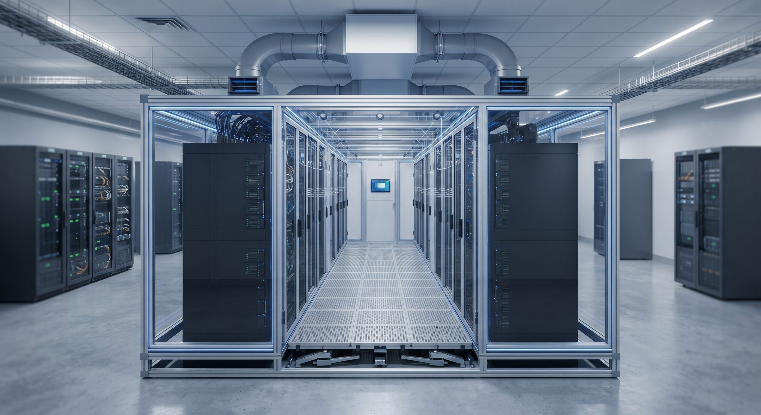
Ceiling-Ducted Hot Aisle Containment with Active Dampers
In this topology, each hot aisle forms a discrete containment pod with a ceiling duct connection to a common return plenum. A motorized damper at the duct interface modulates exhaust flow based on the pod’s differential pressure relative to the room. The CRAH fans maintain a set negative pressure in the return plenum, drawing air through the open dampers. Validation testing should include: (1) step-load testing—rapidly increasing IT load by 30% and verifying damper response within 60 seconds; (2) fan failure simulation—disabling one CRAH fan and confirming that remaining units and dampers maintain positive cold aisle pressure; and (3) sensor fault injection—disconnecting a pressure sensor to verify fail-safe damper positioning (typically 100% open to prevent starvation).
Cold Aisle Containment with Underfloor Active Tiles
For raised-floor CAC deployments, dynamic balancing is achieved through active damper tiles that replace fixed-perforation floor tiles. Each tile contains a motorized louver and a local pressure sensor. The control objective is to maintain a slight positive pressure within the cold aisle enclosure (typically 1-3 Pa relative to the hot aisle) so that any leakage flows outward rather than drawing hot air inward. This configuration is particularly sensitive to underfloor plenum pressure uniformity; the CRAH fan speed must be modulated to maintain sufficient plenum static pressure for all active tiles, with the tile dampers providing local trimming. Commissioning should include a tile-by-tile airflow verification using a flow hood, confirming that each rack position receives its design CFM within ±10%.
Summary
Dynamic air-balance tuning transforms containment from a passive physical barrier into an active thermal management system. For telecom hardware operators, the ROI is quantifiable: eliminating bypass airflow and enabling higher supply air temperatures can reduce cooling energy consumption by 20-40%, while stabilizing ASIC junction temperatures to protect MTBF and deterministic latency performance. The configuration manual is straightforward—seal the envelope, instrument the pressure boundaries, implement cascaded control with rate limiting, and validate against ASHRAE RCI and RTI targets. In an era where edge compute density continues to climb, static containment is no longer sufficient; the fluid dynamics must be tuned dynamically, or the infrastructure will silently waste capacity and compromise reliability.
Leave a comment