
Identifying the Hidden Failure Mode in Submerged Compute Modules
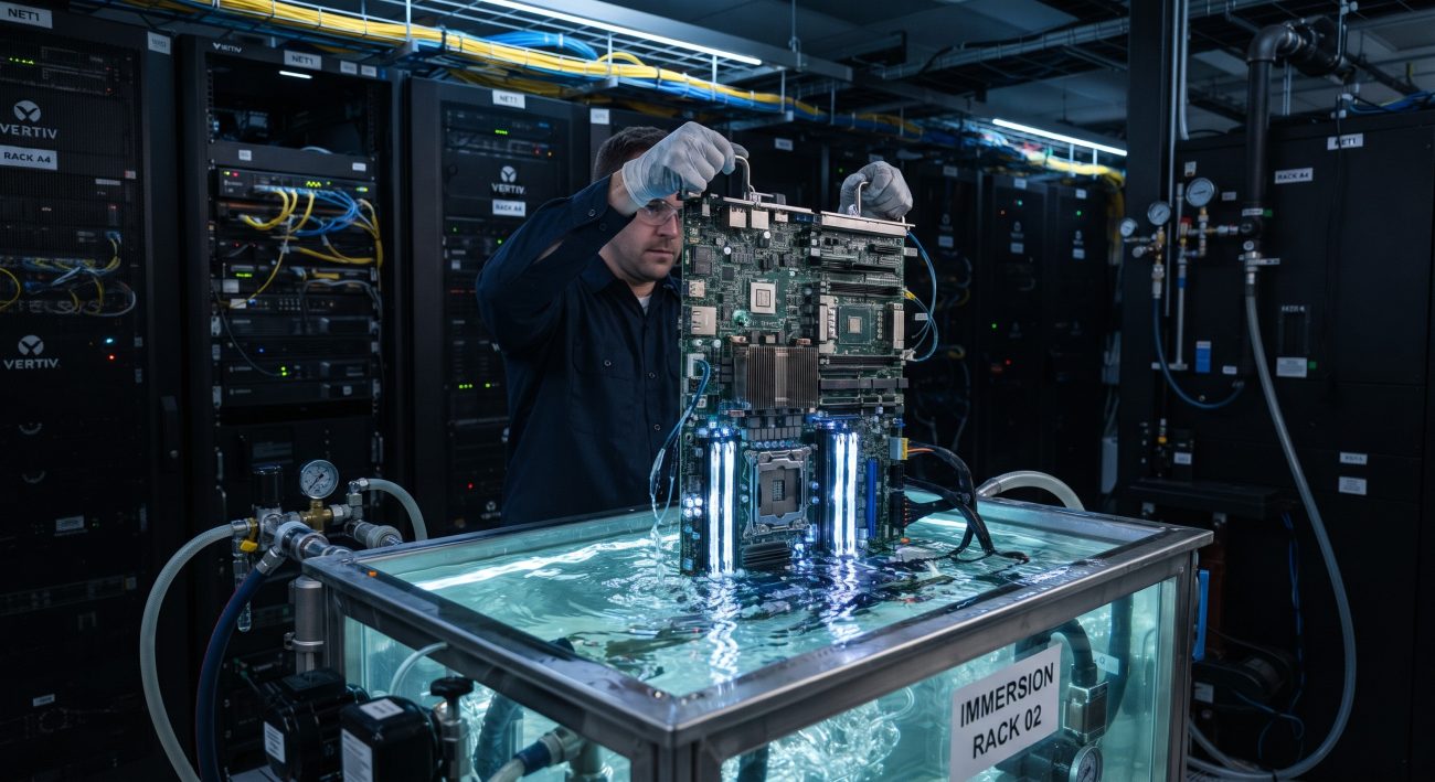
The migration from air-cooled to single-phase immersion liquid cooling (SPLIC) for high-density compute modules is accelerating, driven by the thermal design power (TDP) ceilings of modern ASICs and the relentless push for PUE reduction. While the thermal benefits are well-documented—achieving heat transfer coefficients orders of magnitude higher than forced air—the reliability physics of submerged motherboards introduce a distinct and often underestimated failure mechanism: component delamination. Unlike air-cooled environments where moisture and oxygen are the primary stressors, immersion subjects the printed circuit board (PCB) and its constituent materials to continuous fluid contact, elevated thermal cycling, and unique hydraulic pressures. This manual dissects the root causes of delamination in immersion-cooled compute modules, provides configuration parameters to mitigate risk, and outlines best practices for field deployment based on current IEEE and OCP reliability frameworks.
Solving Latency via Architecture: The Delamination Pathway
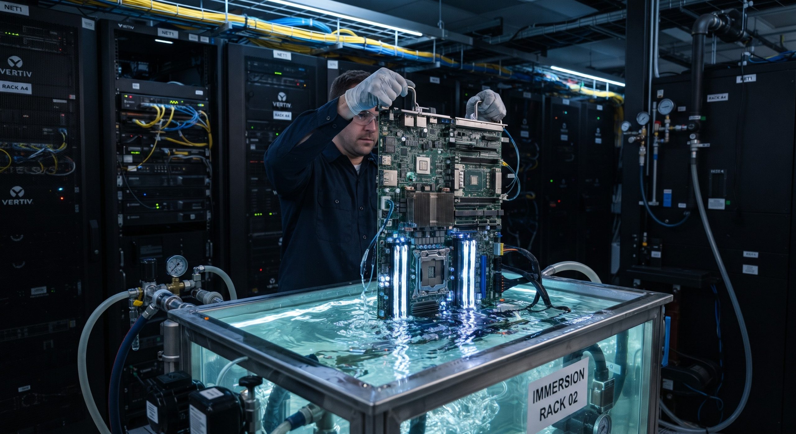
Delamination in a submerged motherboard is not a singular event but a cascading failure that compromises both mechanical integrity and signal integrity. The root cause is often the coefficient of thermal expansion (CTE) mismatch between the laminate, the copper planes, and the solder mask, exacerbated by the fluid environment. When the compute module undergoes power cycling, the Z-axis expansion of standard FR-4 (50–70 ppm/°C above Tg) creates significant stress on plated through-holes (PTHs) and microvias. In air, this stress is partially relieved by convection. In immersion, the fluid’s higher thermal mass and viscosity alter the thermal transient profile, potentially accelerating fatigue at the barrel-to-pad interface .
A more insidious mechanism is hydraulic fatigue driven by trapped fluid. Open or tented vias that are not fully encapsulated can entrap dielectric fluid during the heating phase. As the board cools, the trapped fluid contracts, creating a localized vacuum or internal pressure differential that stresses the via barrel and the surrounding resin. Over thousands of cycles, this hydraulic pumping action can initiate micro-cracks in the resin, leading to localized delamination between the prepreg layers and the copper foil. According to industry PCB design guidelines for liquid cooling, specifying IPC-4761 Type VII via protection (epoxy fill with cap plating) is not optional but mandatory for immersion-destined boards to eliminate this failure mode .
Material Compatibility and Fluid Absorption
The chemical interaction between the dielectric fluid and the laminate is another critical vector. Hydrocarbon-based fluids, while excellent dielectrics, possess higher solvency than fluorocarbons. Prolonged exposure at 45–60°C can cause the polymer chains in the solder mask and the laminate resin to absorb fluid molecules, leading to swelling. This swelling generates shear stress at the interface between the solder mask and the copper traces, eventually causing the mask to lift or the underlying prepreg to delaminate. Research indicates that standard liquid photoimageable (LPI) solder masks may soften or swell in hydrocarbon fluids, whereas the material selection for the laminate must prioritize low absorption rates and high glass transition temperatures (Tg ≥ 180°C) to maintain dimensional stability .
| Key Parameter | Technical Specification / Mitigation Target |
|---|---|
| PCB Laminate Tg | ≥ 180°C (High-performance FR-4 or Megtron-class) |
| Z-Axis CTE (above Tg) | ≤ 35 ppm/°C to minimize PTH fatigue |
| Via Protection Standard | IPC-4761 Type VII (Epoxy fill + Cu cap) |
| Solder Mask Compatibility | Validated for specific fluid (Hydrocarbon vs. Fluorocarbon) |
| Fluid Resistivity | > 1 GΩ·m (per OCP baseline for single-phase) |
| Max Thermal Ramp Rate | ≤ 5°C / minute (Junction to fluid) |
| Surface Finish | ENIG (Nickel barrier prevents Cu diffusion) |
| Inspection Method | SAM (Scanning Acoustic Microscopy) for delamination detection |
Operational Parameter Limits and Configuration Best Practices
To mitigate delamination risks in deployed compute modules, operators must configure the immersion environment within strict parameters that balance thermal performance with material longevity. The following configuration matrix synthesizes data from OCP immersion guidelines and IEEE reliability studies, providing actionable thresholds for enterprise deployment.
Thermal Cycling and Fluid Flow Constraints
The rate of temperature change (dT/dt) during workload ramps is a primary driver of CTE-induced stress. While immersion cooling allows for rapid heat removal, excessively fast ramp rates can shock the laminate. It is recommended to configure BMC/PWM fan curves (in hybrid systems) or CDU flow rates to limit the junction temperature slew rate to ≤ 5°C per minute during high-load transitions. Furthermore, the fluid flow velocity across the motherboard should be maintained within the laminar regime for the specific fluid viscosity; excessive turbulence near the board surface can induce vibration, which, when coupled with thermal cycling, accelerates fatigue cracking at solder joints and delamination at rigid-flex interfaces.
Fluid quality management is equally critical. The accumulation of plasticizers, dust, or moisture in the fluid can lower its dielectric strength and increase its conductivity. While the bulk fluid resistivity may remain above 1 GΩ·m, localized contaminants can concentrate at the board surface, promoting electrochemical migration and corrosion under the solder mask, which manifests as adhesive failure (a form of delamination) between the mask and the copper. Implementing ion exchange filters and monitoring the fluid’s acidity (TAN) are essential operational practices to preserve the integrity of the submerged motherboard over a 5–10 year service life .

Field Deployment Topologies and Validation
In carrier-grade or edge datacenter deployments, the physical orientation of the compute module within the tank influences delamination risk. Modules should be mounted vertically (blade orientation) rather than horizontally to facilitate natural convection and prevent the accumulation of any particulate matter or condensate on the board surface. The use of conformal coatings requires careful evaluation; while they can provide an additional barrier against fluid absorption, improper application can trap solvents or create a secondary interface prone to blistering. For systems utilizing synthetic hydrocarbons, acrylic conformal coatings are generally compatible, whereas polyurethane coatings may degrade.
Validation of delamination resistance should not rely solely on functional tests. Scanning Acoustic Microscopy (SAM) is the industry-standard non-destructive method for detecting interfacial voids and delamination within the PCB stack-up. For enterprise configuration validation, a sample of compute modules should undergo thermal cycling (e.g., JEDEC JESD22-A104, -40°C to +125°C) in an air environment followed by immersion exposure, with SAM inspection performed at intervals to establish a baseline for the specific board design. If SAM equipment is unavailable, cross-sectional polishing of daisy-chained via test coupons provides destructive but definitive evidence of barrel cracks and resin separation.
Summary of Mitigation Strategies
- Design Phase: Mandate IPC-4761 Type VII via fill, specify high-Tg laminates (≥180°C) with low Z-axis CTE (≤35 ppm/°C), and select fluid-compatible solder masks validated per OCP guidelines.
- Operational Phase: Limit thermal ramp rates, maintain fluid cleanliness (particle count and moisture), and monitor for changes in dielectric loss tangent via online TDR if available.
- Validation Phase: Incorporate SAM inspection into the acceptance test procedure (ATP) for immersion-ready compute modules and conduct periodic audits of a sacrificial unit from the production batch.
Conclusion
Submerged motherboard component delamination is a predictable, physics-driven failure mode that becomes increasingly probable as compute density and fluid temperatures rise. By adopting a specification-first approach—selecting PCB materials with low CTE and absorption, enforcing via encapsulation, and controlling the operational environment’s thermal and chemical parameters—telecom operators and systems integrators can unlock the full TCO benefits of immersion cooling without compromising the 10-year MTBF targets expected of carrier-grade infrastructure. The convergence of updated OCP test protocols and emerging IEEE standards for immersion reliability provides the necessary framework; the remaining task is disciplined execution in enterprise configuration and field validation.
Leave a comment