
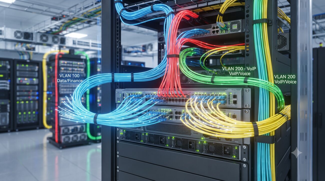
Introduction: The Strategic Imperative of VLAN Segmentation
In the modern enterprise, network sprawl is the enemy of performance, security, and manageability. The proliferation of IoT devices, the shift to hybrid work, and the insatiable demand for bandwidth have rendered traditional flat network architectures obsolete. This is where Virtual Local Area Networks (VLANs) become a critical strategic asset. As defined by IEEE 802.1Q, a VLAN is a logical grouping that segments a physical network into isolated broadcast domains, enabling devices to communicate as if they are on the same physical segment, regardless of their actual physical location . This guide provides a comprehensive, architect-level blueprint for VLAN deployment, covering the technical specifications, configuration logic, and operational best practices required to build a robust, high-performance network.
Core Architecture & Hardware Topology: The Foundation of Logical Segmentation
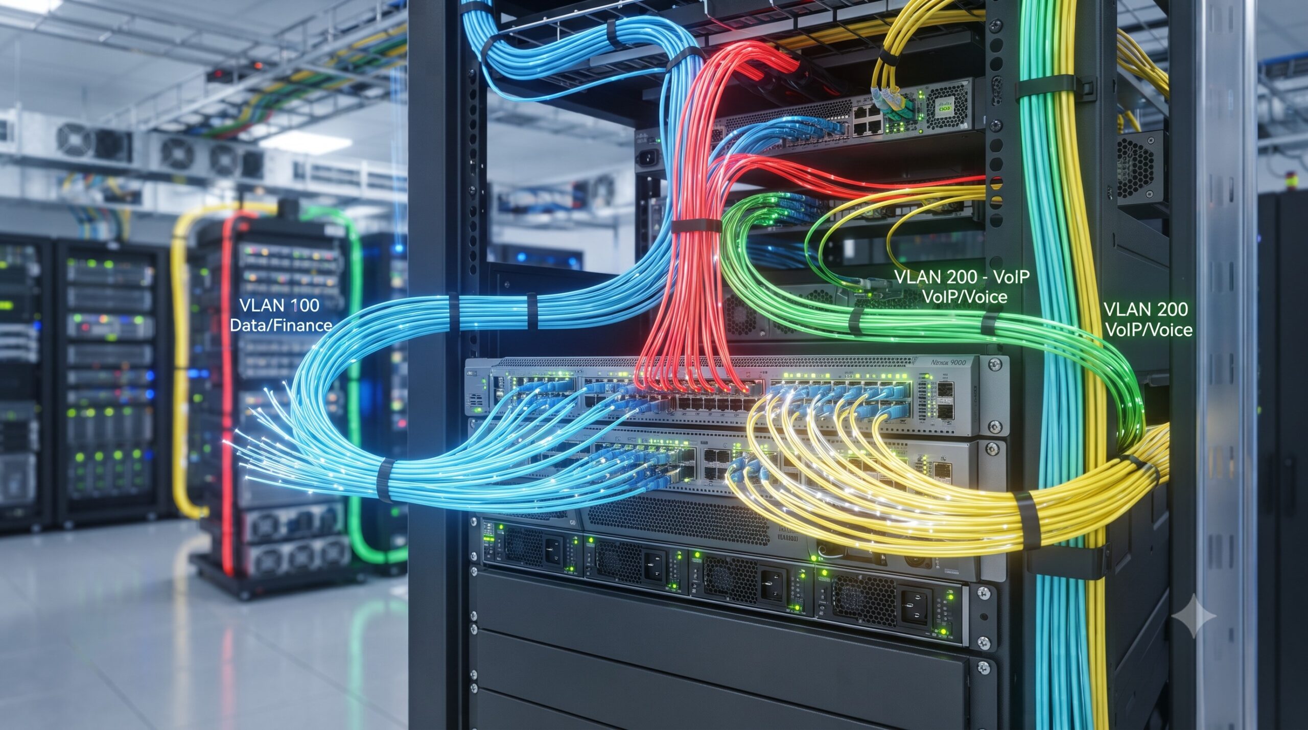
At its heart, VLAN architecture is about mapping logical boundaries onto physical hardware. The segmentation is achieved through port-based assignment, where switch ports are statically assigned to a specific VLAN, or through more dynamic methods . A fundamental concept is the VLAN Trunk, typically implemented using the IEEE 802.1Q standard. A trunk port is a point-to-point link that carries traffic for multiple VLANs between switches or between a switch and a router . This is achieved by VLAN tagging, where a 4-byte tag containing a VLAN Identifier (VID) is inserted into the Ethernet frame header, allowing the receiving device to identify the VLAN of origin . The VID range spans from 1 to 4094, providing ample room for organizational segmentation .
VLAN Port Membership Modes
Understanding port modes is crucial for any network architect. Cisco and other enterprise vendors define three primary port modes :
- Access Port: The interface is an untagged member of a single VLAN. This is the typical configuration for end-user devices like PCs and printers.
- Trunk Port: The interface is a tagged member of multiple VLANs, carrying traffic for all VLANs by default (though this list can be pruned). It also has a Native VLAN, whose traffic is sent untagged to maintain compatibility with legacy devices .
- General Port: A flexible mode defined by IEEE 802.1Q that supports both tagged and untagged memberships .
| Parameter | Technical Specification & Metric |
|---|---|
| VLAN ID Range | IEEE 802.1Q Standard: 1 to 4094 (Extended-range: 1006-4094) |
| STP Virtual Ports (PVST+) | Calculation: (Trunks * Active VLANs on Trunk) + Number of Non-Trunk Ports |
| Default VLAN | VLAN 1 (Carries control plane traffic; best practice is to avoid for data) |
| Trunk Encapsulation | IEEE 802.1Q (Industry standard; adds a 4-byte tag to Ethernet frames) |
| Supported Port Modes | Access, Trunk, General (IEEE 802.1Q), Voice VLAN, Private VLAN |
Deep Dive into VLAN Trunking and Inter-VLAN Routing
To extend a VLAN’s reach across a network, trunk links are essential. However, simply creating a trunk is not enough. A critical consideration is the Native VLAN. By default, most switches use VLAN 1 as the native VLAN. A common, and dangerous, misconfiguration is a Native VLAN mismatch, which can lead to traffic being misrouted or, worse, create a security vulnerability that enables VLAN hopping attacks . Best practice dictates changing the native VLAN to an unused VLAN ID to mitigate these risks .
Furthermore, traffic between different VLANs inherently requires Layer 3 routing. This is where the concept of a Switch Virtual Interface (SVI), also known as a VLAN interface, comes into play. An SVI is a logical interface on a Layer 3 switch that represents a VLAN and is assigned an IP address, enabling routing between VLANs . A Layer 3 switch functions as both a switch and a router, inspecting incoming packets, making routing decisions, and handling routing protocols like OSPF .
Performance and Scalability Limitations
VLANs are not without their resource overhead. A significant factor is Spanning Tree Protocol (STP), which prevents loops by maintaining an instance per VLAN in PVST+ or Rapid PVST+ mode. The STP virtual port count is calculated as: (Trunks * Active VLANs on Trunk) + Number of Non-Trunk Ports. For example, a switch with 40 trunk ports and 100 active VLANs on each would have 4,008 STP virtual ports, consuming substantial CPU and memory resources . This necessitates careful capacity planning.

Security Best Practices and Operational Guidelines
VLANs are a cornerstone of network security, but they are only as strong as their configuration. Several key security considerations must be addressed:
- Avoid VLAN 1: VLAN 1 is the default VLAN on most switches and carries control plane traffic like CDP, STP, and VTP. Using VLAN 1 for user data is a significant security risk and should be strictly avoided .
- Limit Trunk Ports: Trunk ports carry traffic for multiple VLANs and must be physically secured. Ensure DTP is disabled on ports that do not require it to prevent unauthorized trunk establishment .
- Prune Unnecessary VLANs: By default, a trunk port carries all VLANs. Manually pruning VLANs that are not required on a trunk reduces broadcast traffic and improves security .
- Ingress Filtering: Enable ingress filtering on general ports to discard frames from VLANs of which the port is not a member .
- Separate Trust Zones: For networks of significantly different trust levels (e.g., corporate LAN and DMZ), consider using separate physical switches to eliminate the risk of misconfiguration exposing your internal network .
Data-Driven Technical Specifications
For a network architect, the decision to deploy VLANs is backed by specific technical parameters. The table below outlines the key specification limits and performance metrics.
| Parameter | Technical Specification & Metric |
|---|---|
| VLAN ID Range | IEEE 802.1Q Standard: 1 to 4094 (Extended-range: 1006-4094) |
| STP Virtual Ports (PVST+) | Calculation: (Trunks * Active VLANs on Trunk) + Number of Non-Trunk Ports |
| Default VLAN | VLAN 1 (Carries control plane traffic; best practice is to avoid for data) |
| Trunk Encapsulation | IEEE 802.1Q (Industry standard; adds a 4-byte tag to Ethernet frames) |
| Supported Port Modes | Access, Trunk, General (IEEE 802.1Q), Voice VLAN, Private VLAN |
Conclusion: Mastering the VLAN for a Resilient Network
VLAN configuration is a foundational skill for any network architect, but mastering it requires a deep understanding of the underlying technology, the hardware limitations, and the security implications. From the logical isolation provided by port assignment to the complex Layer 3 routing enabled by SVIs, a well-designed VLAN architecture is the bedrock of a high-performance, secure, and manageable network. By adhering to the best practices outlined in this guide—such as avoiding VLAN 1, properly configuring trunks and native VLANs, and understanding STP overhead—you can build a network that scales to meet the demands of the modern enterprise while maintaining operational integrity.

Leave a comment