
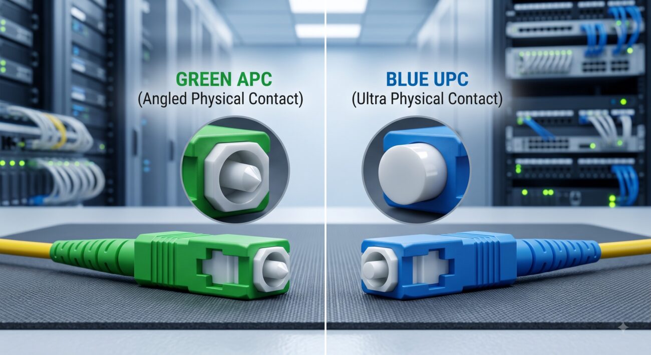
Overview & Thematic Scope: Troubleshooting APC vs UPC Connector Mismatch
In fiber optic networks, mating an Angled Physical Contact (APC) connector with an Ultra Physical Contact (UPC) connector is a critical error that can lead to signal degradation and potential equipment damage. This FAQ guide is designed for network engineers and field technicians troubleshooting reflectance issues caused by APC/UPC mismatch. We cover the technical reasons for incompatibility, methods to identify and verify each connector type, field remedies including the use of hybrid patch cables, and specific procedures for accurate OTDR testing of APC links. All answers are structured to provide clear, actionable steps to resolve connectivity issues and prevent costly errors.
Frequently Asked Questions on APC vs UPC Mismatch Troubleshooting
- Q1: What is the root cause of signal loss when connecting an APC connector to a UPC connector?
- Direct definitive answer: Signal loss occurs because the angled end-face of an APC connector (polished at 8°) physically cannot make proper core-to-core contact with the flat or slightly domed end-face of a UPC connector, creating an air gap and massive misalignment . This physical mismatch results in high insertion loss, which is the loss of optical power. More critically, the anti-reflective properties of the APC are nullified, causing a large portion of the light to be reflected directly back to the source. This leads to a sharp drop in return loss, compromising signal quality and potentially damaging sensitive transmitters .
- Q2: What are the specific risks and potential damage of mixing APC and UPC connectors?
- Direct definitive answer: The primary risks include severe signal degradation, unstable network performance, and potential physical damage to both the fiber connectors and the transceiver optics. Mating an APC connector to a UPC port creates a significant air gap and poor alignment, which increases attenuation and generates strong back-reflections . These reflections can travel back to the laser source in a transceiver, causing power fluctuations and, in high-power applications, can permanently damage the transmitter (TOSA) and receiver (ROSA) interfaces . The physical act of forcing these incompatible connectors together can also scratch or crack the delicate ceramic ferrule end-faces.
- Q3: What is the typical return loss difference between a correct APC/APC connection and a mismatched APC/UPC connection?
- Direct definitive answer: A correct APC-to-APC connection boasts an industry-standard return loss of -65 dB or better, minimizing reflections, while a mismated APC/UPC connection will exhibit severely poor return loss, often in the range of -14 dB to -25 dB . For context, the minimum recommended return loss for a UPC-to-UPC connection is -55 dB . The dramatic drop from -65 dB to -14 dB signifies that a massive amount of light is being reflected back to the source, which is a clear indicator of a faulty and problematic connection. This is often visible on an OTDR trace as a highly reflective event .
- Q4: How can I visually identify an APC connector vs. a UPC connector on a fiber patch cable?
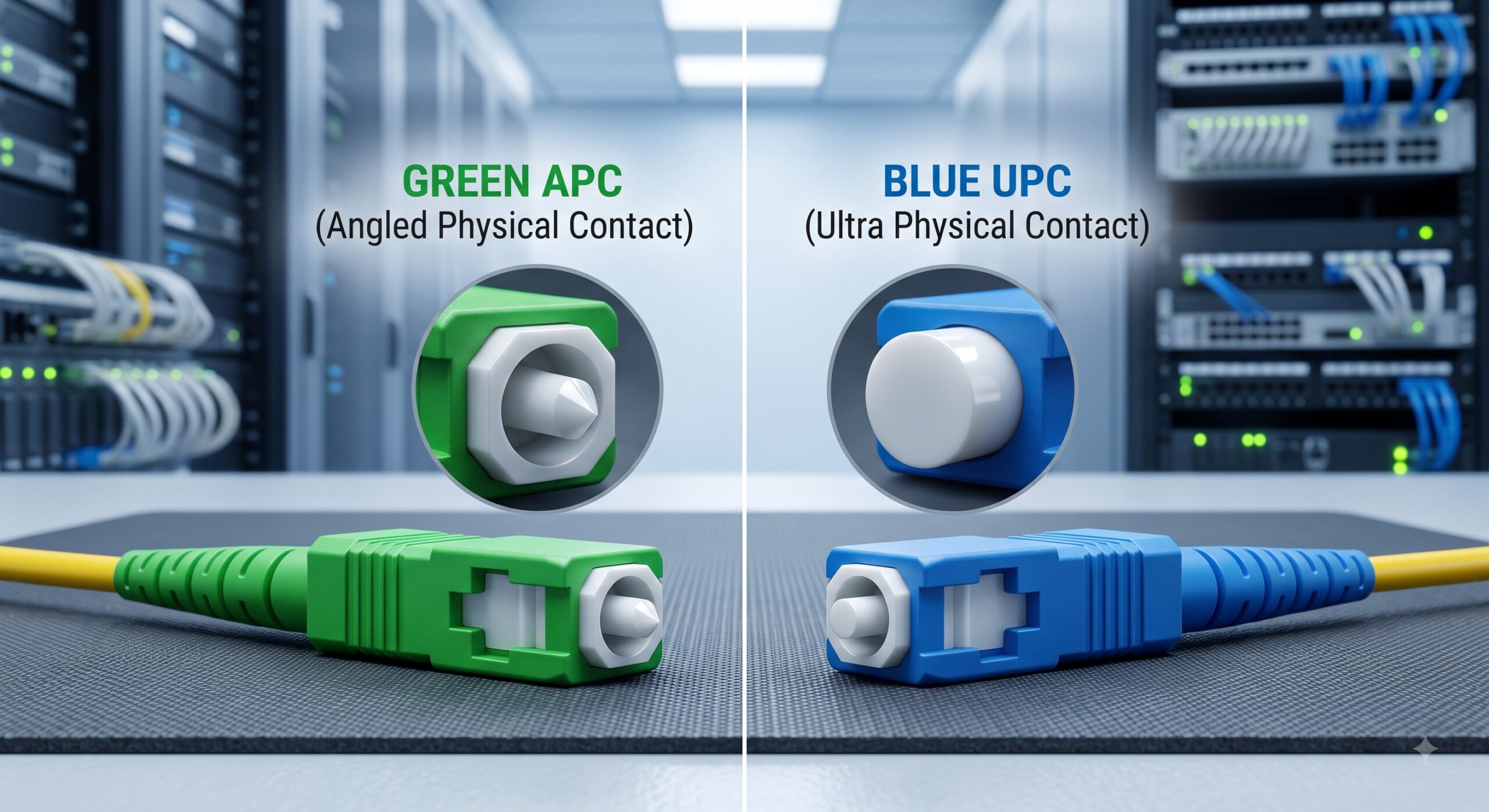
- Direct definitive answer: The easiest way to identify these connectors is by color and a physical inspection of the ferrule end-face . An APC connector body and boot are typically green. If you look at the tip of the ferrule, the end-face will be visibly angled. In contrast, a UPC connector is usually blue or may have a blue boot, and its ferrule end-face will appear flat or slightly curved. This simple visual check is critical for preventing accidental mismatches in the field.
- Q5: What is the recommended field remedy if I need to connect equipment with an APC port to a cable with a UPC connector?
- Direct definitive answer: The proper and safe field remedy is to use a hybrid or conversion patch cable that has an APC connector on one end and a UPC connector on the other . This specialized cable ensures that each end is physically compatible with its respective equipment or panel, while the fiber inside transmits the signal correctly. Never use an adapter or forcibly connect mismatched cables; this will cause performance issues and can damage the equipment’s optical interfaces.
- Q6: Why does an OTDR show an APC connection as a non-reflective event, and how does this affect testing?
- Direct definitive answer: An OTDR (Optical Time-Domain Reflectometer) will classify a properly mated APC connector as a non-reflective event, similar to a splice or bend, because the angled polish effectively directs reflected light out of the core, resulting in negligible backscatter . This characteristic improves testing accuracy by reducing dead zones. However, it also requires a specific testing procedure. To test an APC link, you must use launch and receive cables with APC connectors. A mismatched APC-to-UPC connection will defeat this benefit, creating a highly reflective event on the OTDR trace that can produce echoes and obscure the true loss of the link, making it difficult to pinpoint other issues .
- Q7: In which network scenarios is it critical to use APC connectors instead of UPC to avoid reflectance issues?
- Direct definitive answer: APC connectors are critical in high-bandwidth, long-distance, and high-wavelength applications that are highly sensitive to back-reflections, such as FTTx (Fiber-to-the-x), Passive Optical Networks (PON), and RF video transport networks . In these scenarios, the ultra-low return loss provided by APC (-65 dB) is non-negotiable to prevent signal distortion and laser instability. Specifically, applications using wavelengths above 1500nm, like those for RF video, are particularly susceptible to reflectance, making APC the standard choice for service providers and cable companies.

Leave a comment