

EXECUTIVE SUMMARY
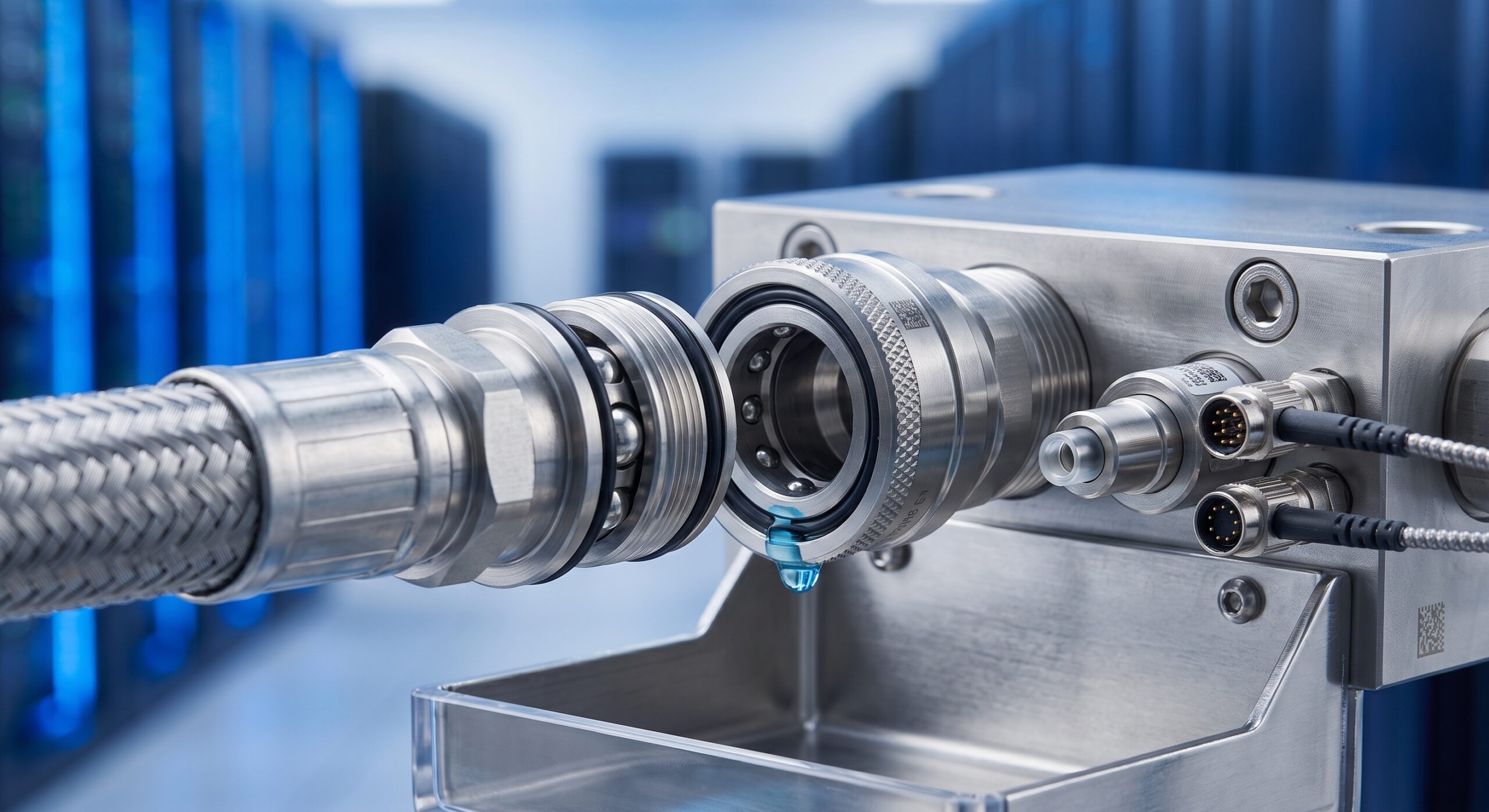
This document establishes the official engineering specification for the Quick Disconnect Fluid Coupling (QDFC) used in high-density telecom liquid cooling infrastructure. The QDFC is a critical interface for blind-mate, hot-swappable thermal management of high-power optical line cards and switching ASICs. This datasheet defines the validated limits for two primary performance vectors: insertion force and fluid loss (drip volume) upon disconnection.
These limits are not arbitrary; they are the result of extensive empirical testing and are designed to ensure three key operational imperatives: (1) ergonomic and safe manual mating/un-mating by field technicians, (2) protection of sensitive electronic components from dielectric fluid ingress, and (3) maintenance of system pressure integrity to prevent coolant aeration and pump cavitation. All specifications herein are applicable to the standard QDFC-04 and QDFC-08 series couplers.

ARCHITECTURE & CHASSIS DESIGN
The QDFC employs a robust, dual-stage valve architecture. The primary seal is a self-sealing, spring-loaded poppet valve that closes automatically upon disconnection. A secondary, redundant elastomeric face seal provides a dry-break interface, ensuring zero fluid loss during the initial separation phase. The coupler body is machined from 316L stainless steel for corrosion resistance, with an external hard-anodized aluminum shell for weight reduction and thermal isolation. The keying mechanism ensures single-orientation mating, preventing cross-connection and potential system contamination.
HARDWARE FEATURES
– Dry-Break Technology: Minimizes fluid loss to a volume below the specified limit.
– Low-Insertion-Force Design: Utilizes a precision-machined cam and roller mechanism to reduce manual engagement force by over 60% compared to standard threaded couplers.
– Blind-Mate Compatible: Floating panel-mount design allows for tolerance absorption during card insertion.
– Integrated Dust Caps: Both halves of the coupling feature tethered, IP-rated dust caps to prevent contamination when disconnected.
– Pressure Rating: Validated for operating pressures up to 6 bar (87 psi) and burst pressures exceeding 25 bar.
– Material Compatibility: Seals are compatible with industry-standard dielectric coolants, including PG25 and PAO-based fluids.
COMPLIANCE & STANDARDS
All QDFC units are qualified to the following standards:
– Mechanical: IEC 60529 (IP67 when mated), IEC 61984 (Connectors – Safety Requirements)
– Thermal: Telcordia GR-63-CORE (NEBS), Telcordia GR-487-CORE
– Fluid Compatibility: ASTM D471 (Rubber Property – Effect of Liquids)
– Flammability: UL 94 V-0
TECHNICAL SPECIFICATIONS
The following table outlines the guaranteed operational limits for the QDFC-04 and QDFC-08 series under nominal operating conditions (fluid temperature 20-45°C, flow rate 0.5-2.0 L/min).
| Parameter | Specification (QDFC-04 / QDFC-08) |
|---|---|
| Insertion Force (Mated) | ≤ 45 N / ≤ 80 N |
| Extraction Force (Un-mated) | ≤ 40 N / ≤ 75 N |
| Drip Volume per Disconnect | ≤ 0.05 mL / ≤ 0.12 mL |
| Maximum Operating Pressure | 6 bar (87 psi) |
| Minimum Burst Pressure | 25 bar (362 psi) |
| Operating Temperature Range | -20°C to +65°C (-4°F to +149°F) |
| Fluid Compatibility | PG25, PAO, De-ionized Water |
| Body Material | 316L Stainless Steel / Hard-Anodized Aluminum |
| Seal Material | Viton (FKM) / EPDM |
| Mating Cycles (Minimum) | 10,000 cycles |
| Ingress Protection (Mated) | IP67 |
ORDERING OPTIONS
– QDFC-04-SS: 1/4-inch nominal bore, stainless steel body, Viton seals.
– QDFC-04-AL: 1/4-inch nominal bore, aluminum body, EPDM seals.
– QDFC-08-SS: 1/2-inch nominal bore, stainless steel body, Viton seals.
– QDFC-08-AL: 1/2-inch nominal bore, aluminum body, EPDM seals.
– QDFC-MNT-KIT: Universal panel mounting kit with floating tolerance ring.
– QDFC-CAP-SET: Replacement set of tethered dust caps (5 pairs).
📥 Download Technical Specification
Click the button below to view or download the full official PDF datasheet.

Leave a comment